CE351
2020 Fall
Lab 7: Elegoo Smart Car
Sophie Turner
sjturner@fortlewis.edu Project: Elegoo Smart Car Kit 3.0v
1. Introduction The
purpose of this lab was to code an Elegoo Smart Car Kit 3.0v to complete
different tasks. The robot was coded to detect some distance using an ultrasonic
sensor to avoid obstacles, track a line of electric tape, and to use a remote
to turn the car left, right, move forward, and backwards. The different tasks
were put together to code the car to avoid obstacles and be able to drive
around by itself.
2. Materials and Methods For this lab an Arduino Uno R3 and an Elegoo Smart Car Kit 3.0v was assembled and coded for different tasks. An
ultrasonic sensor (HC-SR04) was used to sense distance and a servo
motor was also used. The kit uses a L298 Dual H-Bridge Motor Driver to
control the wheels. The line tracker was made possible by using three
pairs of IR sensors to sense the line. An IR remote was used to
control the car and to change between different modes. For a more
detailed
material and methods section visit http://www.yilectronics.com/Tutorials/Arduino_Basics/Tutorial_7_robotCar/robotCar.html
3. Results
Task 2:
A ultrasonic sensor measures distance. The sensor is used for obstacle
avoidance for Task 8. The sensor was coded to display the distance in
centimeters to the serial monitor.
Figure 1. Code for the ultrasonic sensor.
Figure 2. Code for the ultrasonic sensor.
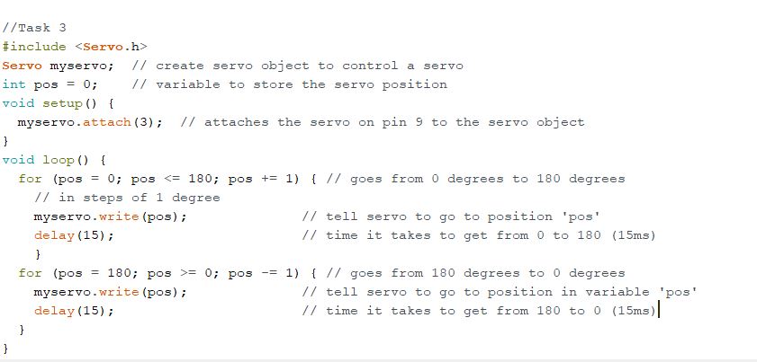
Task 3: A servo
motor was used to rotate the ultrasonic seniors 0 to 180 degrees.
Figure 3. Video
demonstrating the servo motor rotating from 0-180 degrees.
Figure 4. Code to rotate the servo motor.
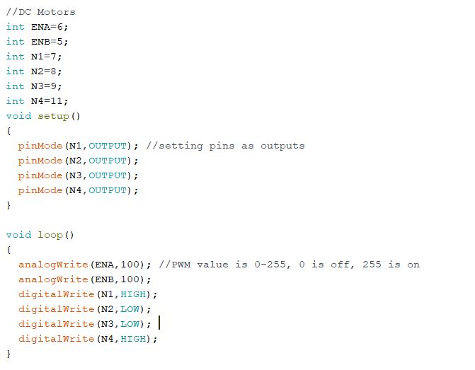
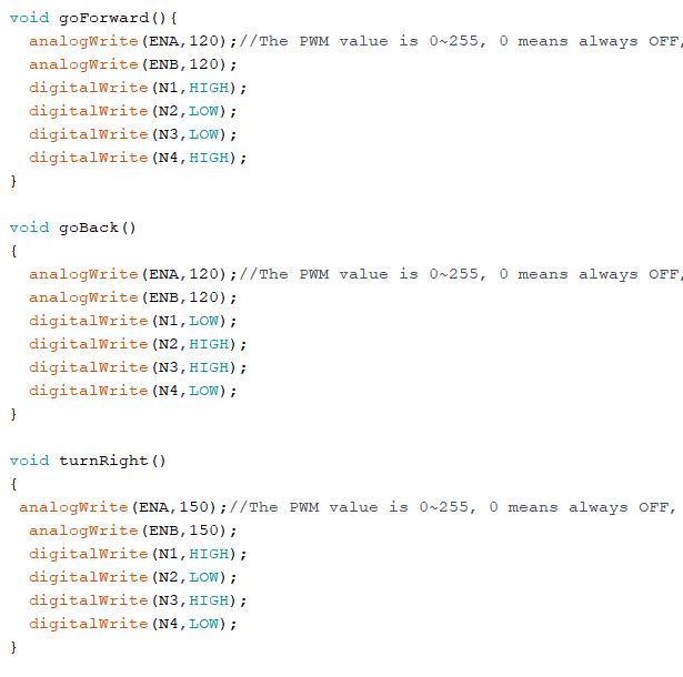
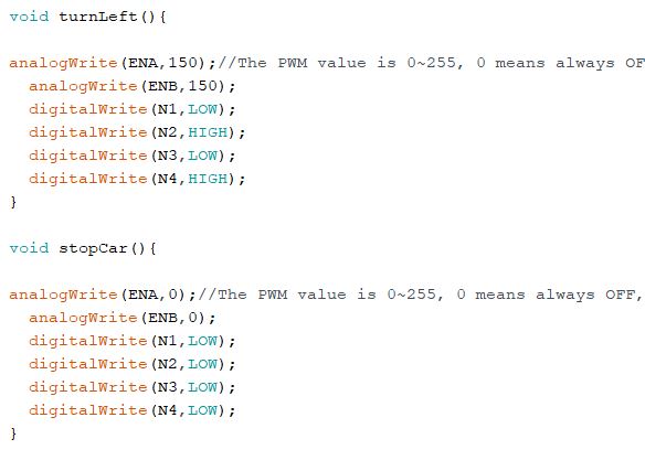
Task 4: DC
motors were used to rotate the wheels of the robot car. The
driver can control the motor RPM and the direction of rotation. The
following code and video show the car going forward. The car can
turn left, right and move backwards by modifying the code.
Figure 5. Video demonstrating the DC motors.
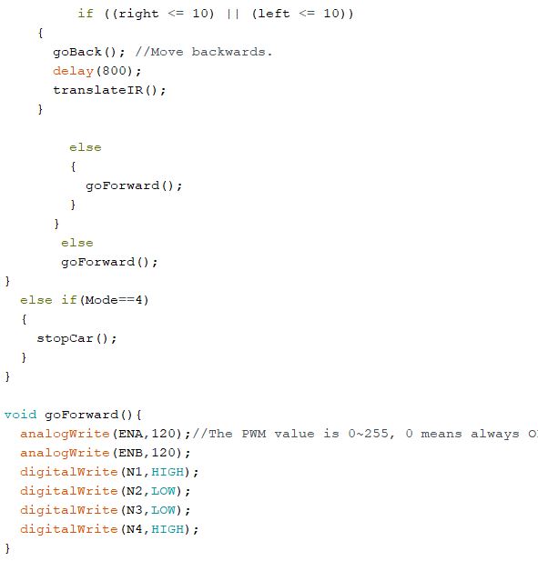
Figure 6. Code to program the DC motors.
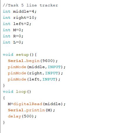
Task 5: Three
IR sensors were used to code the car to follow a line. When there is a
reflection from the white paper, the serial monitor outputted 1. When the IR sensors
'sensed' the line, the serial monitor would read 0.
Figure 7. Video demonstrating the use of IR emitter-receiver sensors.
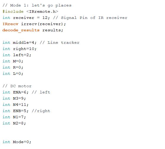
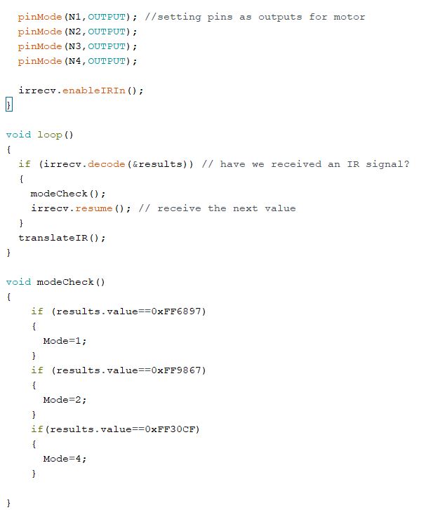
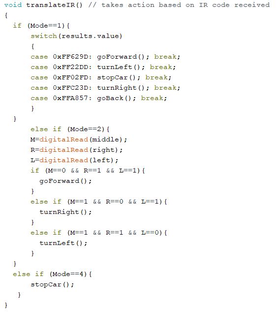
Figure 8. Code to track a line. Task 6: An
IR remote was used to switch between different modes. When '1' was
pushed, the car is controlled using the up, down, right, and left
arrows. The video below demonstrates the car's movement.
Figure 9. Video demonstrating the car turning and moving forwards and backwards.
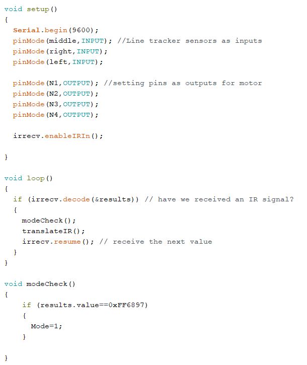
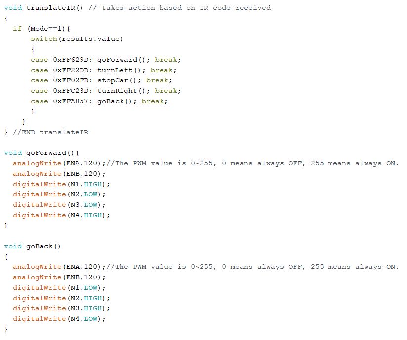
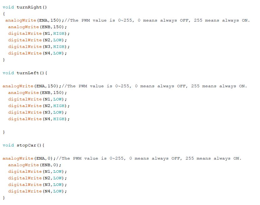
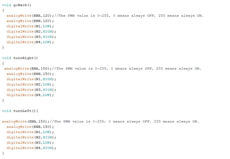
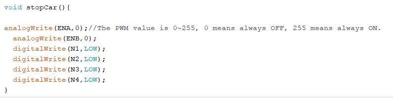
Figure 10. Code
to turn the car left, right, forwards, and backwards. Task 7: The car would track the line of electric tape when '2' was pushed on the remote.
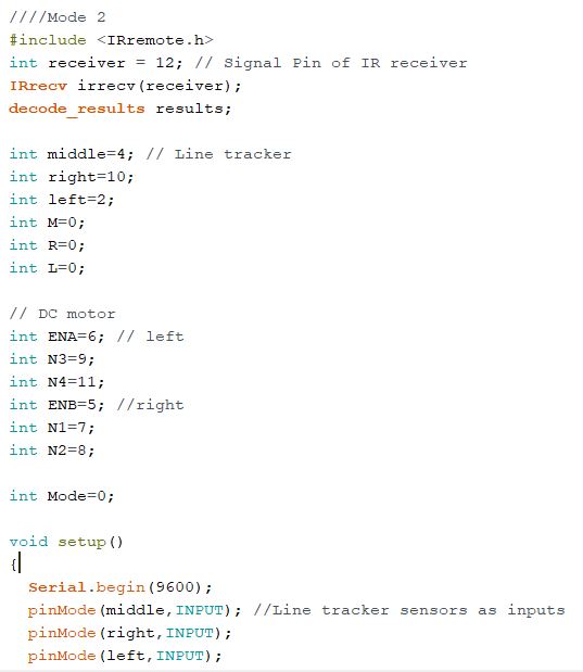
Figure 11. Video demonstrating the car tracking the line.
Figure 12. Code for the line tracking mode.
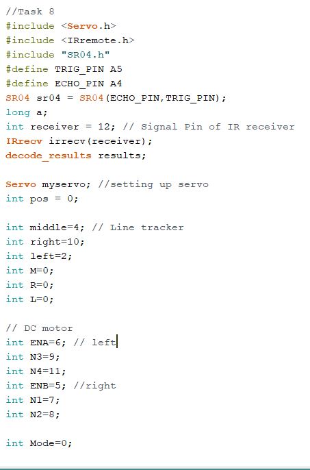
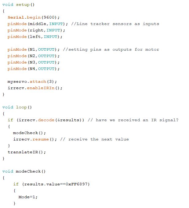
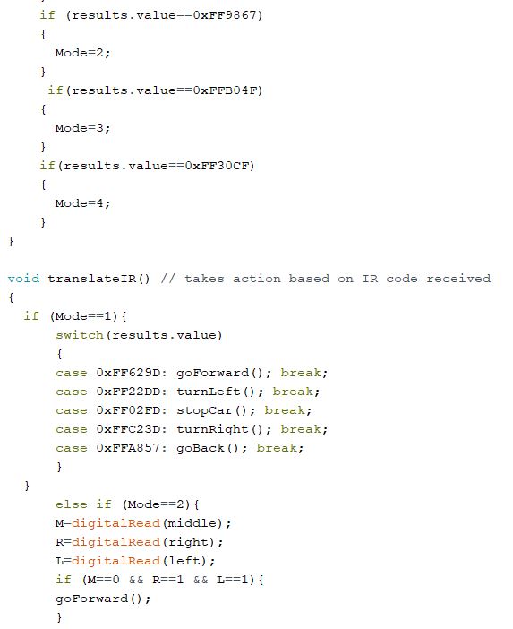
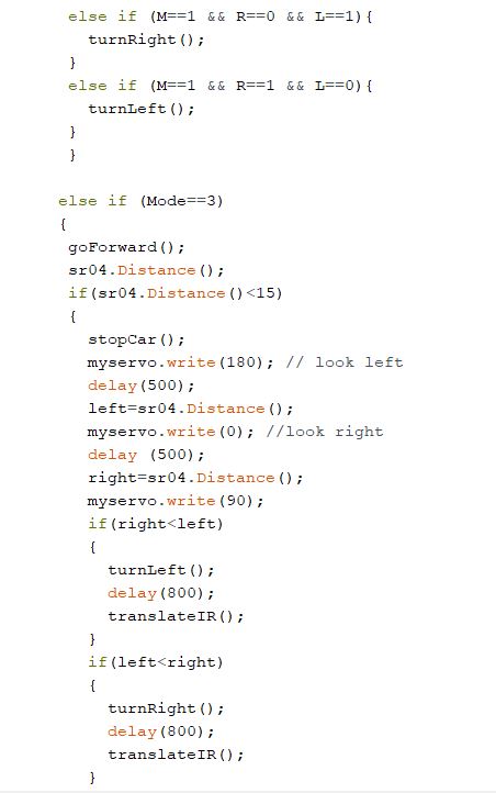
Task 8: The purpose of
this challenge was to implement obstacle avoidance into the code. The car will
sense an object in front, look left, right then decide which way to turn based
on the distance measured from the ultrasonic sensor. In the video below, the
remote is used to transition the car into each mode: driving mode, line
tracking mode, obstacle avoidance, and stopping the car.
Figure 13. Video demonstrating all 4 modes.
Figure 14. Code for the
obstacle avoidance task.
4.
Discussion
The tasks were
completed successfully. I ran into difficulties with the IR remote and IR
sensors being finicky. The obstacle avoiding mode worked but setting up a maze
for the car to work through was difficult. The car was not able to make a
sensible decision when trying to go into the maze. In the video the car
kept sensing objects around, so it turned out of the maze to the open area. For
future recommendations the course should be set up in a larger space without
carpet. Other than having limited space for the course, all the tasks were
completed. Different sensors and motors worked together to create a realistic scenario and applications for the future.