Task
1:
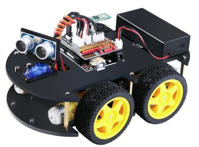
To assemble the car, please follow the tutorials in the following video
series. Please take GOOD care of the small parts of the car when you
assemble it.
There are more
tutorials/demos uploaded to YouTube by other users. Feel free to use
your favorite ones.
2. Test
the sensors and motors used in the car 2.1 The
ultrasonic sensor (the SR04 zip
library) Ultrasonic sensors are great
for distance measurements. The distance information can be used for
obstacle avoiding when it is used in a robot car. The HC-SR04 is a good
candidate of this type of sensor.
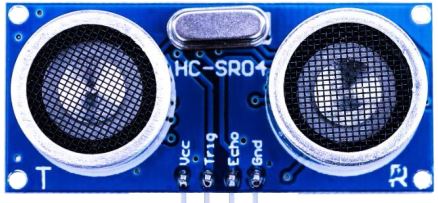
HC-SR04 provides 2 cm - 400
cm non-contact measurement with an accuracy of 3 mm. This module
consists of an ultrasonic transmitter, a receiver, and the control
circuit.
There are four pins to be
connected to the Arduino board on this SR04 module. VCC, GND, Trig, and
Echo. The Trig pin receives the signal from Arduino to send the sound
signal out. The Echo pin will be waiting for any echo of the sound
signal just sent. Arduino has a timer inside to tell the time
difference between the Trig and the Echo signal. Given that the speed
of sound is 340 m/s, the test distance between the SR04 and the
obstacle to be tested can be calculated by Test Distance = (Time
Difference x Speed of Sound) / 2.
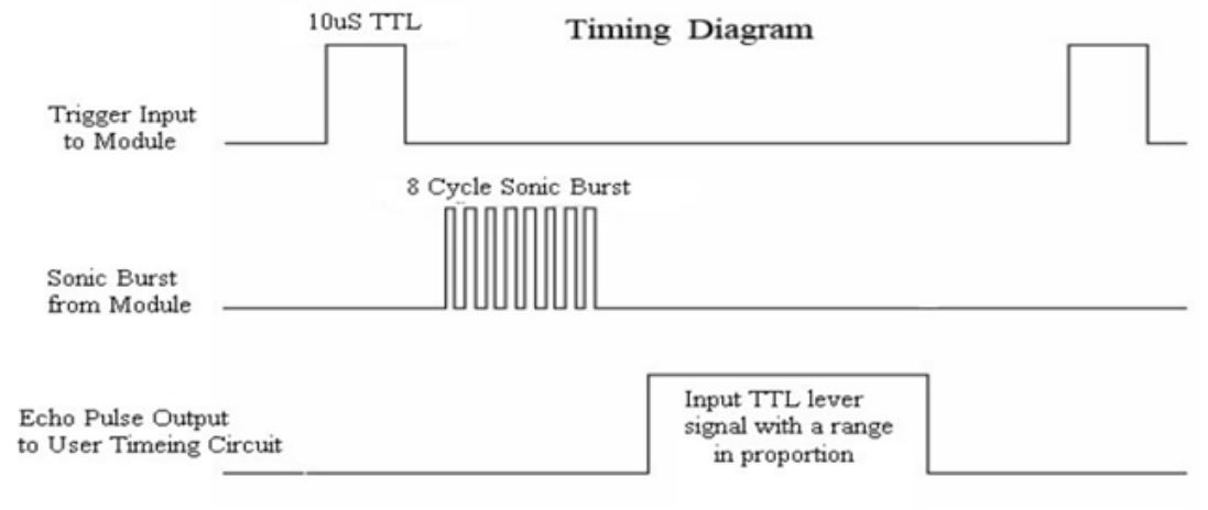
A short pulse of 10 us from
Arduino is used as the Trig signal. After received the Trig signal, the
ultrasound module will send an 8 cycle burst of ultrasound at 40 kHz
and then wait for the echo. When the echo is received, the Echo pin
will be turned on and your Arduino will be able to detect this logic
One.
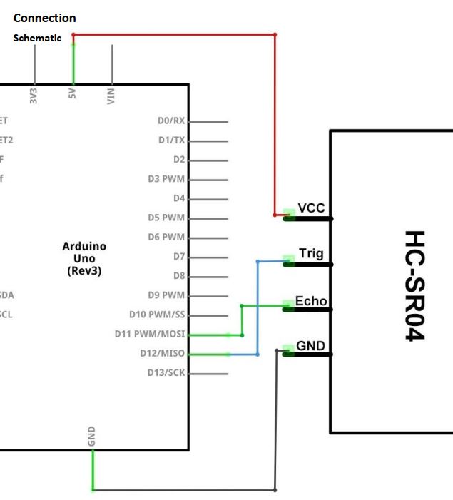
Make the following connections:
Use the example code here and watch the
video for the demonstration.
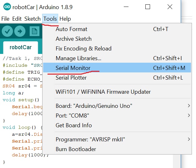
Please note that, the serial monitor is an embedded function in the
Arduino IDE to show you the data being received from the USB port (the
board) by your PC.
My demonstration:
Task
2: Just repeat what I
did in the video above. Take screenshotes or videos for your report. You will
use the same ultrasonic sensor in the robot car kit.
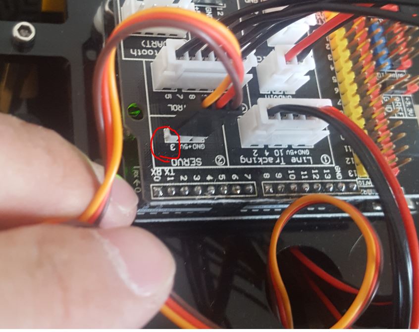
The SR04 ultrasonic sensor is connected to a servo motor. Servo is a
type of geared motor that can only rotate 180 degrees. It is controlled
by sending electrical pulses from your UNO R3 board. These pulses tell
the servo what position it should move to. The Servo has three wires,
the brown one is the ground wire, the red one is the power wire (5V),
and the orange one is the signal wire which is connected to the Digital
Pin 3 on the Arduino board of the car kit.
Task
3: Understant the code
and repeat it on your side. Take VIDEOs for your report.
2.3 The DC
motors
The DC motors are not
directly powered by the 5V power supply from the Arduino board. To run
the motor for a long period of time requires a lot more power that the
5V DC on board can provide, and at the same time, it will generate lots
of heat which needs to be dissipated asap to protect the ICs.
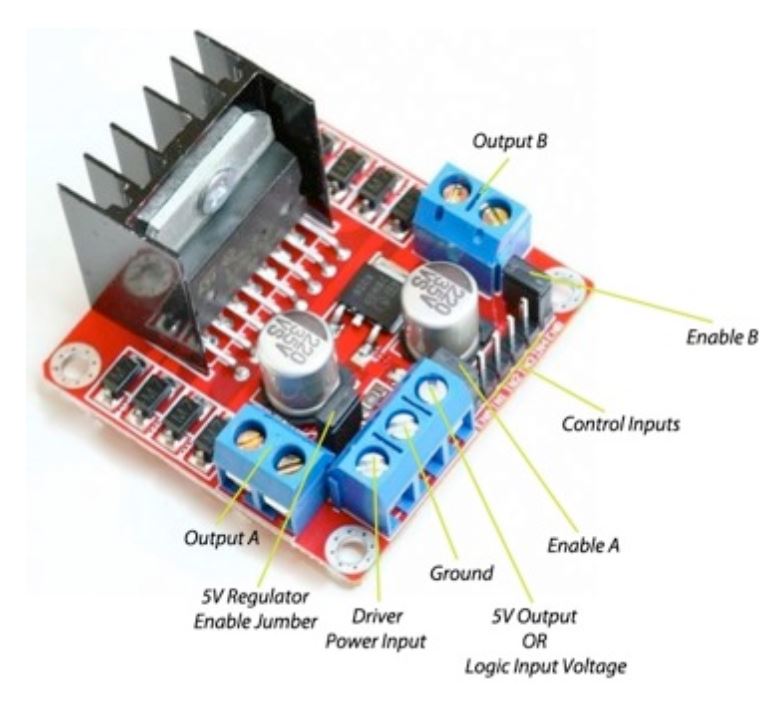
The robot car kit uses L298
Dual H-Bridge Motor Driver module (datasheet) to control the DC motors on the
car.
This driver module is based
on L298N H-bridge, a high current, high voltage dual full bridge driver
manufactured by ST company. It can drive up to 2 DC motors 2A each. It
can also drive one stepper motor or 2 solenoids. The driver can control
both motor RPM and direction of rotation. The RPM is controlled using
PWM input to ENA or ENB pins, while of rotation direction is controlled
by suppling high and low signal to N1-N2 for the first motor or N3-N4
for second motor. This Dual H-Bridge driver is capable of driving
voltages up to 46V.
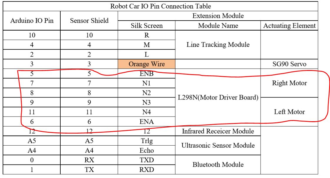
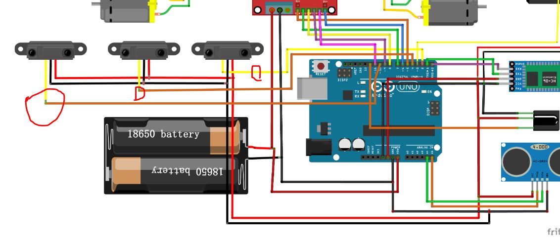
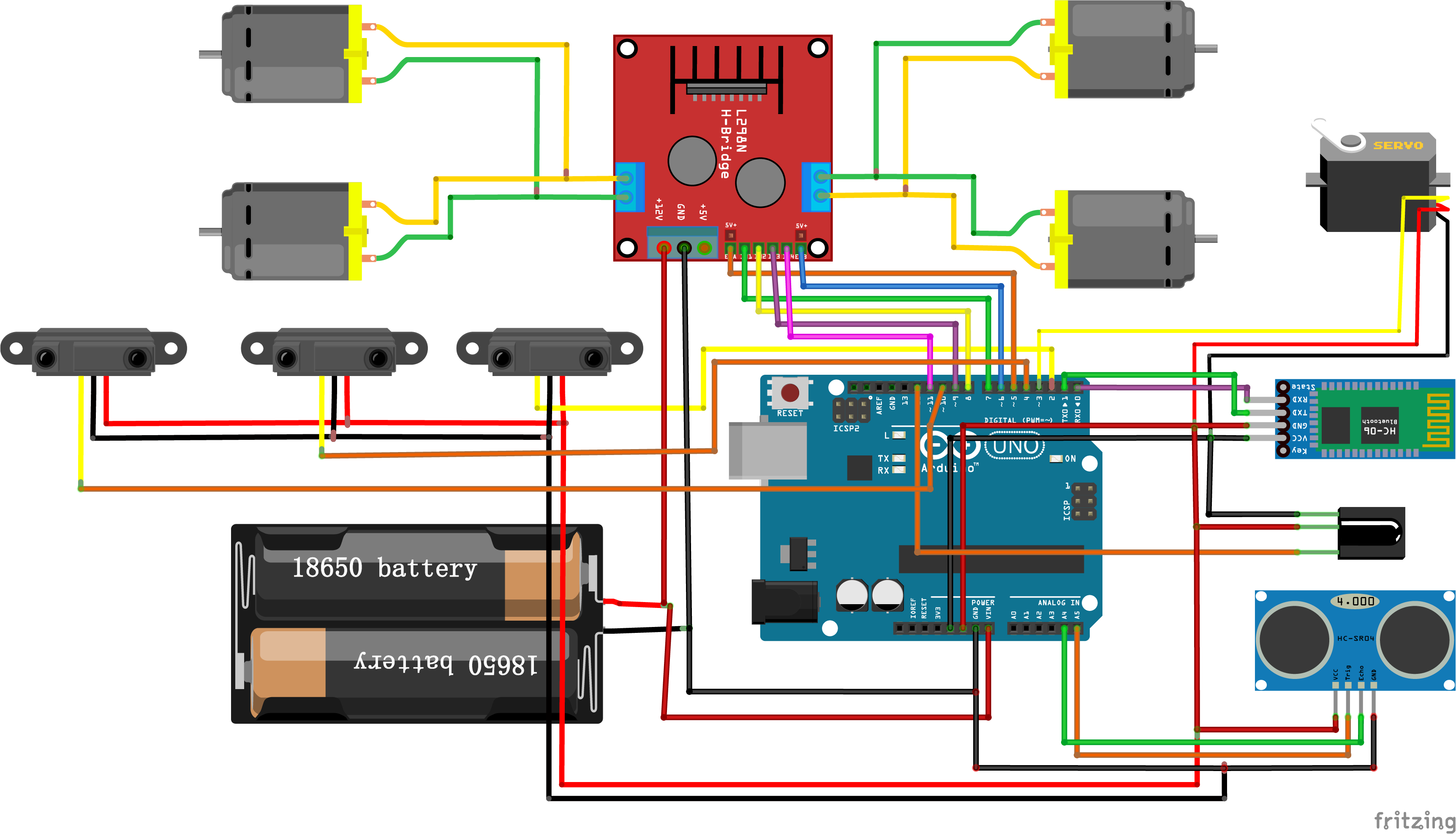
The connections of the car
can be found in this figure and the Pin Table. A snapshot from the Pin
Table.
Since the driver can only
control two or two sets of motors at the same time (because the design
of the L293 IC) and the car has FOUR wheels, I synchronized the left two motors and the right two motors.
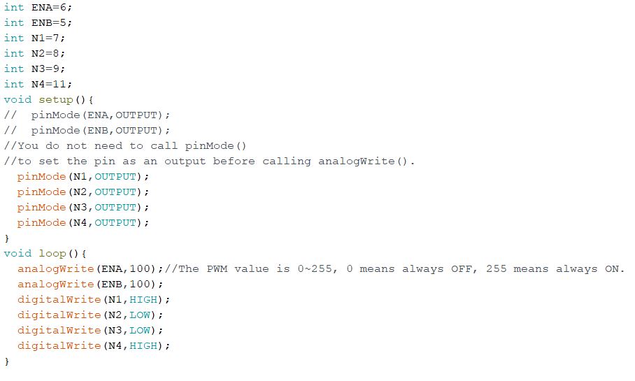
Now, let's design a code to
turn on and off the motor on both sides. By reading the Pin Table, I
coded up the first motor driving program to simply turn on the motors:
The 'analogWrite()' function
is for the PWM module in Arduino.
What
is PWM
PWMstands
for Pulse Width Modulation and it is a technique used in controlling
the brightness of LED, speed control of DC motor, controlling a servo
motor or where you have to get analog output with digital means.
Before
going further, let’s discuss some terms associated with PWM. TON
(On Time): It is the time when the signal is high. TOFF
(Off Time): It is the time when the signal is low. Period:
It is the sum of on time and off time.
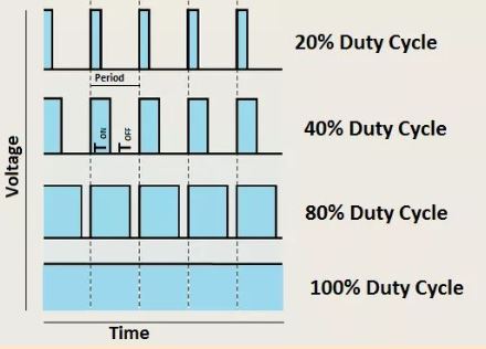
Duty Cycle: It is the percentage of time when the signal was high
during the time of period.
If you use the PWM wave to adjust the
BRIGHTNESS of an LED,
at 50% duty cycle and 1Hz frequency, the led will be high for half a
second and will be low for the other half second. If we increase the
frequency to 100Hz (100 times ON and OFF per second), then the led will
be seen glowing at half brightness by the human eye.
Use the same principle, we
can use the PWM wave to control the speed of a DC motor. The motor gets
speeding up if you Enable it for longer time but Disable it for shorter
time. All these Enable and Diable pulses are oscillating very quickly
so it is not actually ON and OFF. Instead, the real power received by
the motor decreases if the ON time is shorter.
Task
4: Use the example code to turn on the motors of the car, take VIDEOs for the report. Please note
the following things: 1. After the Arduino on the car being programmed,
unplug the USB cable and lift the car off the table before you turn on
the switch on the Battery's box. 2. Make sure the battery is fully
charged. They are rechargable batteries so do not toss them when they
are drained out. 3. Always lift the car before you run the motor to
avoid the car falls off the table.
2.4 The
line tracker
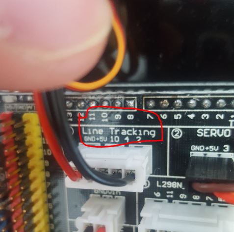
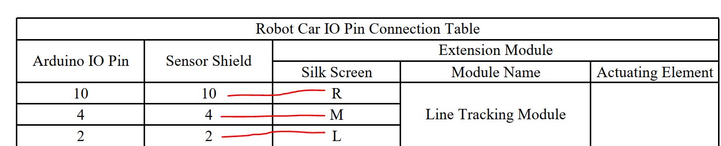
You can easily find the
connectors for the 'Line Tracking' modules on
the shield board:
There are FIVE wires to be
connected to the header. The 5V power supply, the GND, and the three
signal pins: 10, 4, 2. Let's take a look at the datasheet for more
information about the three pins.
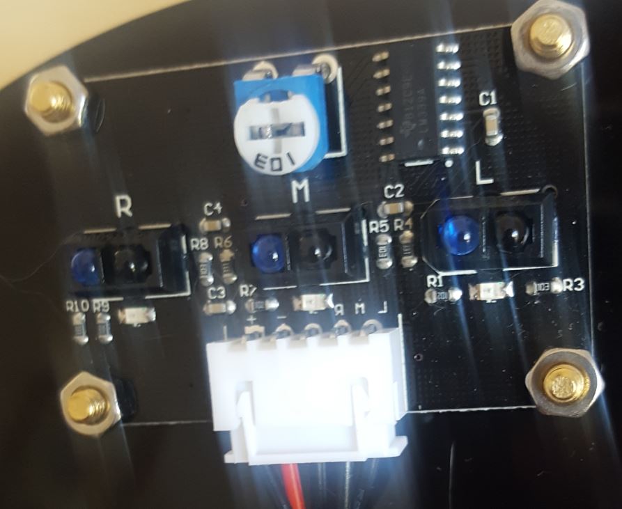
Flip the car, you will see
the Three Pairs of the IR sensors.
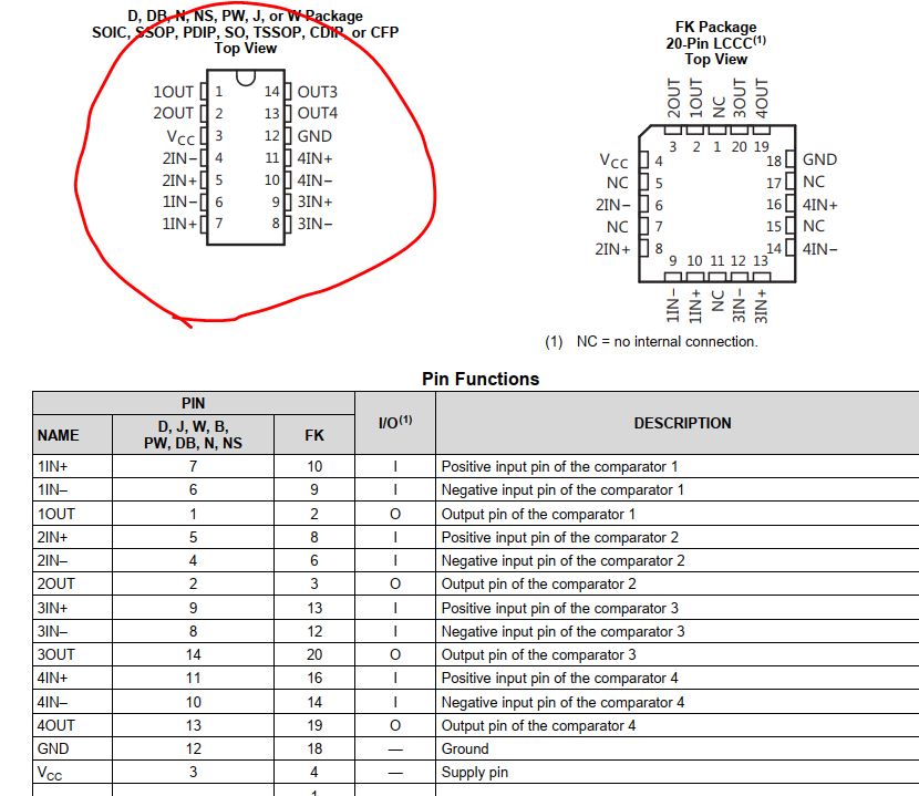
The central control IC is
LM399 comparator (datasheet).
The yellow lines are signal
lines from the IR sensor's board. Refer
to the ENGR 201 lab, if you forget how a comparator works. You do not need to
build the ciruit to make work, instead, you only need to use the Arduino board to process the
signal from the Yellow lines using Arduino.
Let's design a small testing
program to see what the signal looks like.
Use the example code to test
all the three IR emitter-receiver pairs on your side (example code): Watch my demonstration video:
Task
5: Repeat my work in
the demonstration video and use the similar method to test the Right
and the Left IR emitter-receiver pairs.
Now, we have tested all the
sensors and motors on the car. It is not mysterous to us any more.
Let's utilize these powerful sensors to make this car smart enough for
the line tracking and the obstacle avoiding challenges.
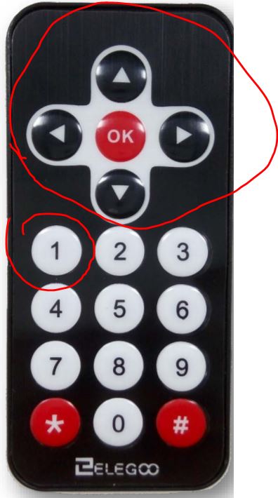
3. The final smart car tournament 3.1 Mode
1: Let's go places :-)
UP: go forward
DOWN: go backward
LEFT: turn to the left
RIGHT: turn to the right
OK: stop
Press key '1' to enter into this mode.
The brief demonstration video:
Here is
my original code partially provided
to you. You do not have
to follow my strategy to design this
program but if you do need the help from this example just use it. (I
deleted several sections in it).
Task
6: Complete the code for Mode 1: Only after pressing '1' to
enter Mode 1, then go places!
3.2 Mode 2: The Line Tracker
Design the code to merge Mode 1 and Mode 2 together so when the car is
powered up, you can switch the mode by simply press keys on the remote
controller without re-program Arduino.
Watch my demo video below:
Task
7:
For Mode 2, complete the code for the car for the 'Go Places' and the 'Line
Tracker' mode. You must use the remote controller to switch the modes.
3.3 Mode
3: The Obstacle Avoider (No Example Code Provided)
Task
8:
Embed this Obstacle Avoidance strategy into your entire code. The final
demonstration must be done in ONE Sketch (one sketch covers all the
three modes).
A demonstration video can be found here:
Complete Task 1 - 8 and submit your report to the website.