CE351
2020 Fall
Lab 6: Accelerometer - MPU 6050 and the I2C communication protocol
Sophie Turner
sjturner@fortlewis.edu Accelerometer - MPU 6050
and the I2C Communication Protocol
1. Introduction
The purpose of
this lab was to use the I2C serial communication protocol to connect
slaves to
a master slave using two wires. The master can write data to the slave
or
receive data from it using addressing to call on a slave. In this lab
the
MPU6050 was coded to display the acceleration in the X, Y, and Z
direction on
the Arduino serial plotter. The MPU6050 was also used as a gyroscope to
calculate the angular speed about the X, Y, and Z axis and display the
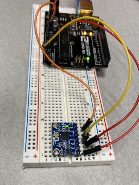
measurements on the serial plotter. The MPU6050 was connected to the
Arduino by connecting the Serial Data pin to A4 and the Serial Clock
was connected to A5.
2. Materials and Methods
An Arduino Uno R3 was used for this lab as well as a MPU6050. The
MPU6050 was coded to display the acceleration in the X, Y, Z direction
on the Arduino serial plotter as well as the angle about the X, Y, and
Z axis on the serial plotter. For a more detailed methods section visit
http://www.yilectronics.com/Tutorials/Arduino_Basics/Tutorial_6_I2C_Accelerometer/I2C_SPI.html
3. Results
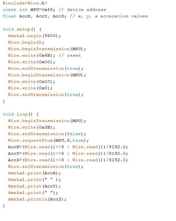
The code below translates digital data into a ±4g range. The code also displays
the acceleration in the X, Y, and Z directions on the serial plotter. Figure
1. Schematic for the MPU6050. Figure 2. Code to generate figures
for the accelerometer.
The
following video demonstrates acceleration in the X, Y, Z direction on the same monitor (X (blue), Y (red), and Z(Green)) .
Figure 3. Accelerometer in X, Y, Z
directions.
The
video below shows the accelerometer moving in the x direction.
Figure 4. Accelerometer moving in the
X direction
The
video below demonstrates the accelerometer moving in the y direction.
Figure 5. Accelerometer moving in the
Y direction
Figure 6 video demonstrates the accelerometer moving in the z direction.
Figure 6. Accelerometer moving in the
Z direction
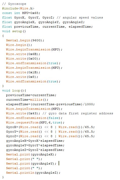
The code below translates digital data into ±500deg/sec range. The code also displays
the angular speed around the X, Y, and Z axis on the serial plotter. Figure 7. Code to generate figures for the gyroscope.
The
following video demonstrates the X, Y, Z angles on the same monitor (X (blue), Y (red), and Z(Green)).
Figure 8. Gyroscope tilting around
the X, Y, Z axes
Figure 9 video demonstrates the gyroscope rotating around the x-axis.
Figure 9. Gyroscope rotating around the X-axis.
Figure 10 video demonstrates gyroscope rotating around the y-axis.
Figure 10. Gyroscope rotating around the Y-axis.
The following video demonstrates the angle from the gyroscope when rotating around the Z-axis.
Figure 11. Gyroscope rotating around the Z-axis.
4.
Discussion
This lab displayed the acceleration in the X, Y, and Z directions as
expected. The gyroscope also outputed correct graphs on the serial
monitor. In
this lab I was able to gain experience using the MPU6050 and using the
I2C communication protocol. The master was the Arduino and the slave
was the MPU6050 in this lab.