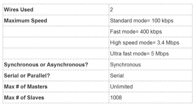
I2C combines the best
features of SPI and UARTs. With I2C, you can connect multiple slaves to
a single master (like SPI) and you can have multiple masters
controlling single, or multiple slaves. This is really useful when you
want to have more than one microcontroller logging data to a single
memory card or displaying text to a single LCD. Like UART
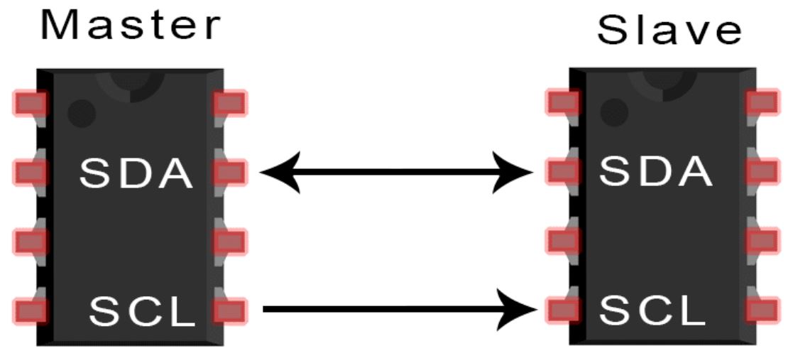
communication, I2C only uses two wires to transmit data between devices:
SDA (Serial Data) – The line
for the master and slave to send and receive data. SCL (Serial Clock) – The line
that carries the clock signal.
I2C is a serial communication
protocol, so data is transferred bit by bit along a single wire (the
SDA line). Like SPI, I2C is synchronous, so the output of bits is
synchronized to the sampling of bits by a clock signal shared between
the master and the slave. The clock signal is always controlled by the
master.
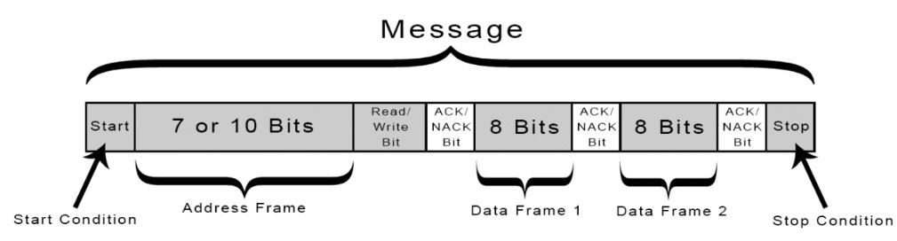
With I2C, data is transferred
in messages. Messages are broken up into frames of data. Each message
has an address frame that contains the binary address of the slave, and
one or more data frames that contain the data being transmitted. The
message also includes start and stop conditions, read/write bits, and
ACK/NACK bits between each data frame:
Start
Condition: The SDA
line switches from a high voltage level to a low voltage level before
the SCL line switches from high to low. Stop
Condition: The SDA
line switches from a low voltage level to a high voltage level after
the SCL line switches from low to high. Address
Frame: A 7 or 10 bit
sequence unique to each slave that identifies the slave when the master
wants to talk to it. Read/Write
Bit: A single bit
specifying whether the master is sending data to the slave (low voltage
level) or requesting data from it (high voltage level). ACK/NACK
Bit: Each frame in a
message is followed by an acknowledge/no-acknowledge bit. If an address
frame or data frame was successfully received, an ACK bit is returned
to the sender from the receiving device.
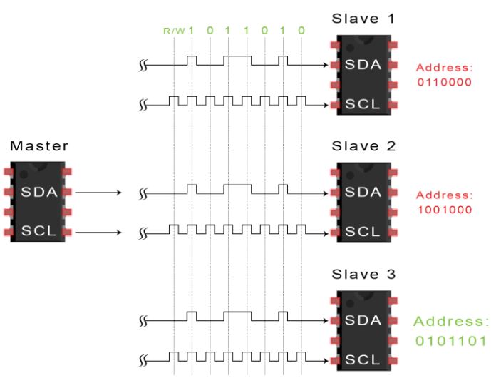
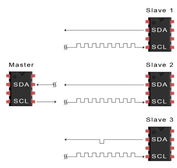
ADDRESSING
I2C doesn’t have slave select
lines like SPI, so it needs another way to let the slave know that data
is being sent to it, and not another slave. It does this by addressing.
The address frame is always the first frame after the start bit in a
new message. The master sends the address of the slave it wants to
communicate with to every slave connected to it. Each slave then
compares the address sent from the master to its own address. If the
address matches, it sends a low voltage ACK bit back to the master. If
the address doesn’t match, the slave does nothing and the SDA line
remains high.
READ/WRITE
BIT The address frame includes a
single bit at the end that informs the slave whether the master wants
to write data to it or receive data from it. If the master wants to
send data to the slave, the read/write bit is a low voltage level. If
the master is requesting data from the slave, the bit is a high voltage
level.
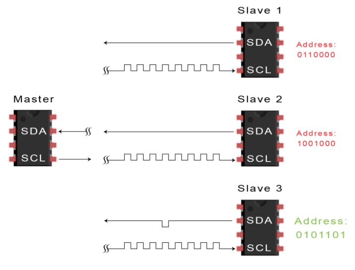
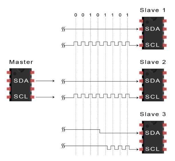
THE DATA
FRAME After the master detects the
ACK bit from the slave, the first data frame is ready to be sent. The
data frame is always 8 bits long, and sent with the most significant
bit first. Each data frame is immediately followed by an ACK/NACK bit
to verify that the frame has been received successfully. The ACK bit
must be received by either the master or the slave (depending on who is
sending the data) before the next data frame can be sent.
After all of the data frames
have been sent, the master can send a stop condition to the slave to
halt the transmission. The stop condition is a voltage transition from
low to high on the SDA line after a low to high transition on the SCL
line, with the SCL line remaining high.
STEPS OF
I2C DATA TRANSMISSION
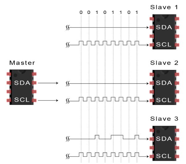
1. The master sends the start
condition to every connected slave by switching the SDA line from a
high voltage level to a low voltage level before switching the SCL line
from high to low. The master sends each slave the 7 or 10 bit address
of the slave it wants to communicate with, along with the read/write
bit:
Each slave compares the
address sent from the master to its own address. If the address
matches, the slave returns an ACK bit by pulling the SDA line low for
one bit. If the address from the master does not match the slave’s own
address, the slave leaves the SDA line high.
The master sends (Write
Request) or receives (Read Request) the data frame:
After each data frame has
been transferred, the receiving device returns another ACK bit to the
sender to acknowledge successful receipt of the frame:
To stop the data
transmission, the master sends a stop condition to the slave by
switching SCL high before switching SDA high:
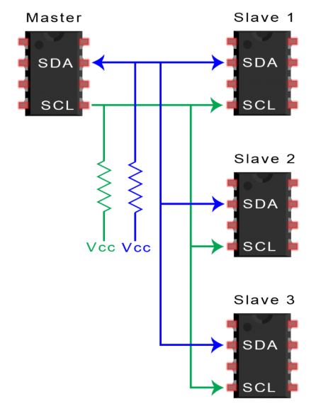
Because I2C uses addressing,
multiple slaves can be controlled from a single master. With a 7 bit
address, 128 (27) unique address are available. Using 10 bit addresses
is uncommon, but provides 1,024 (210) unique addresses. To connect
multiple slaves to a single master, wire them like this, with 5k-20k
Ohm pull-up resistors connecting the SDA and SCL lines to Vcc:
ADVANTAGES
Only uses two wires
Supports multiple masters and multiple slaves
ACK/NACK bit gives confirmation that each frame is transferred
successfully
Hardware is less complicated than with UARTs
Well known and widely used protocol
DISADVANTAGES
Slower data transfer rate than SPI
The size of the data frame is limited to 8 bits
More complicated hardware needed to implement than SPI
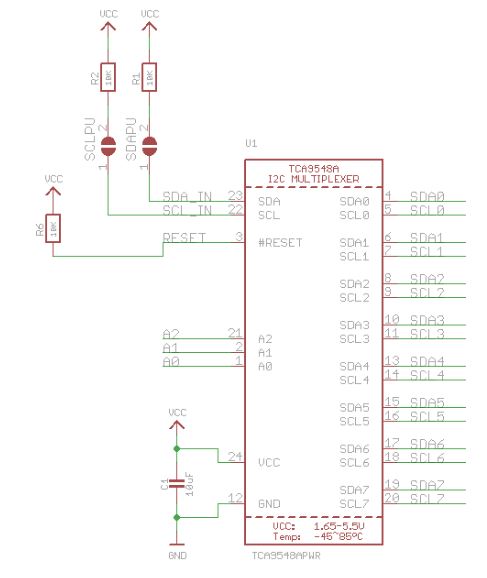
Have to use a I2C Multiplexer to communicate with devices that have a same address.
A typical I2C MUX shematic:
2.
Implement acceleration measurement using the Arduino UNO and
the MPU6050 Accelerometer/Gyroscope 2.1 Accelerometer only
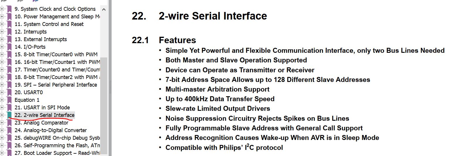
In the data
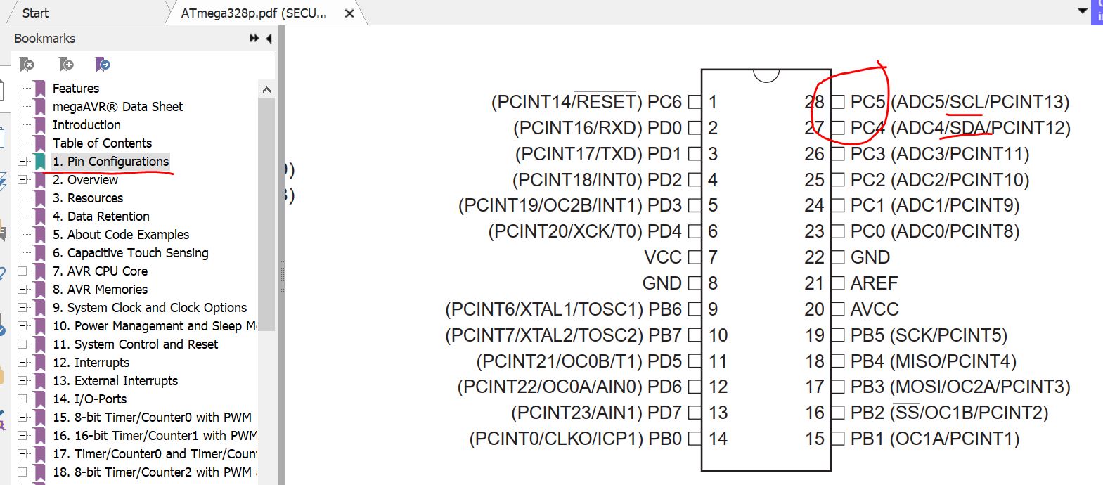
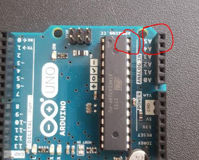
sheet of the microcontroller, go to the page for 'pin
configurations', indentify the two pins for the I2C communication:
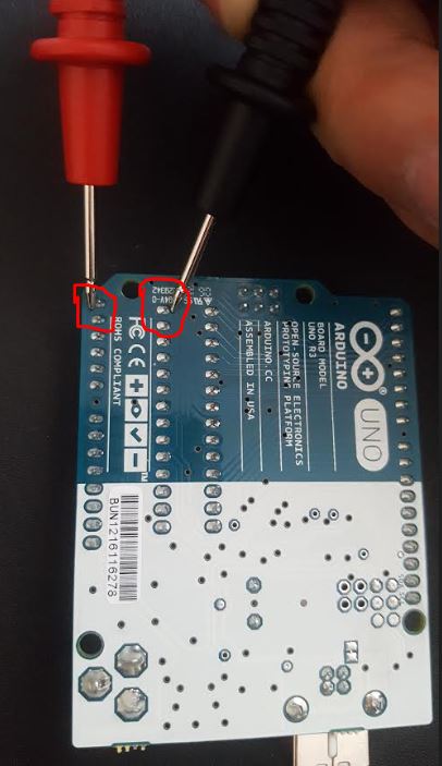
Turn the dial of the
multimeter to Continuity Test mode (). It will
likely share a spot on the dial with one or more functions, usually
resistance (Ω). With the test probes separated, the multimeter’s
display may show OL and Ω.
If the two spots you probe
using the multimeter gives you a beap sound, it means the two spots are
electrically connected.
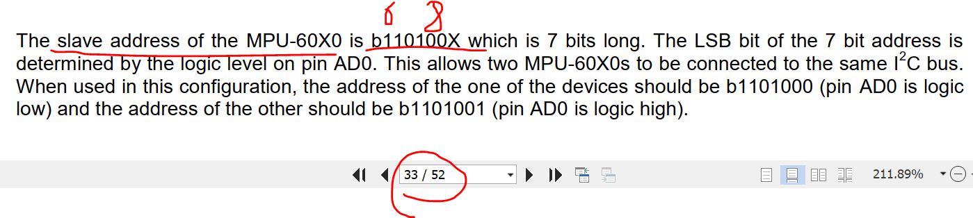
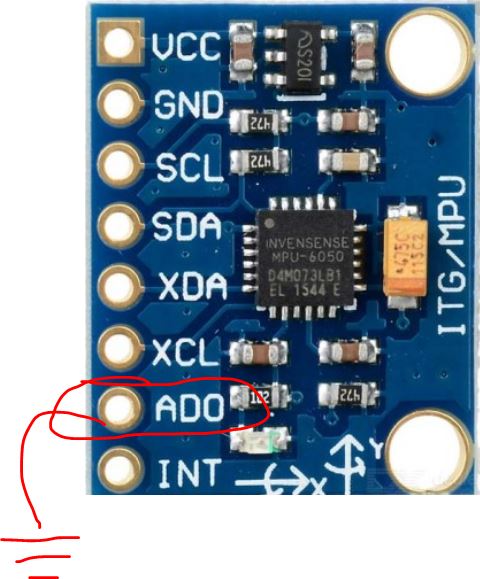
The address of the device is
a 7-bit binary number 0110 100x, if you ground AD0, the address of the
device will be 0110 1000.
You do not need to connect
the 'INT', 'XDA', and 'XCL' pins on the MPU6050 to your Arduino board.
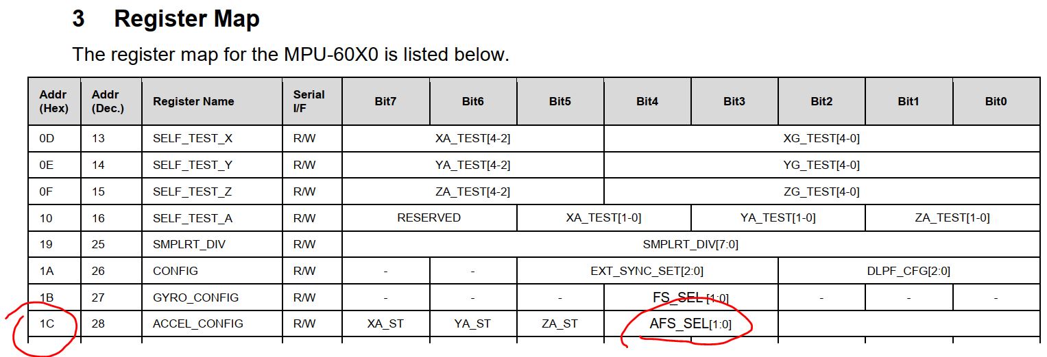
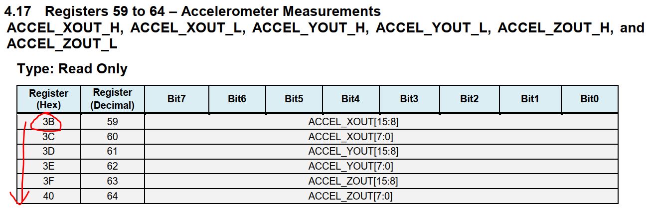
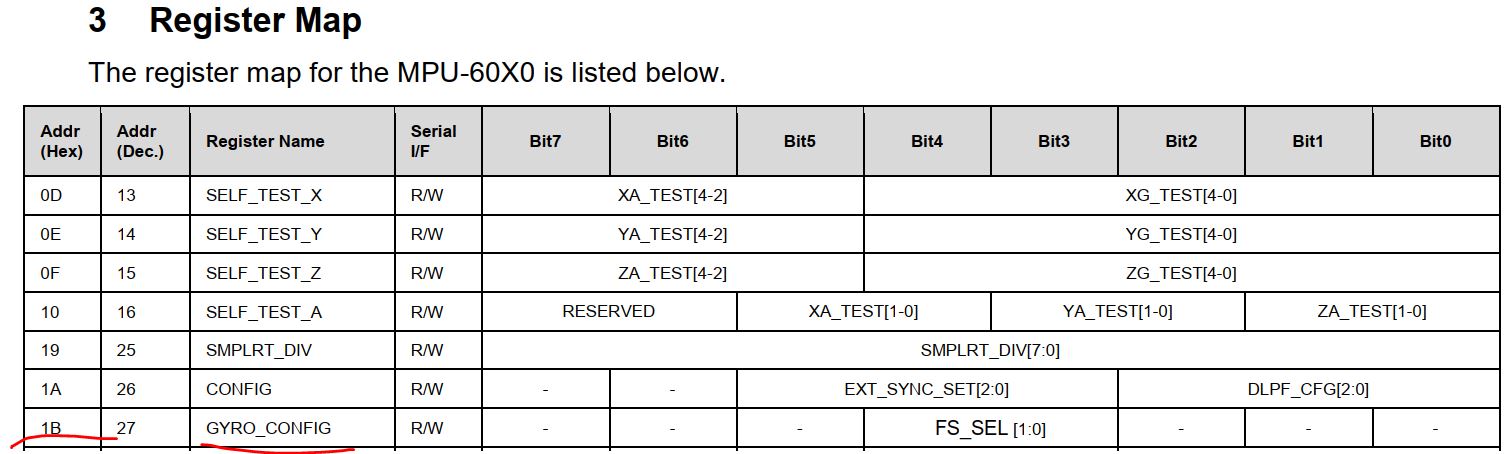
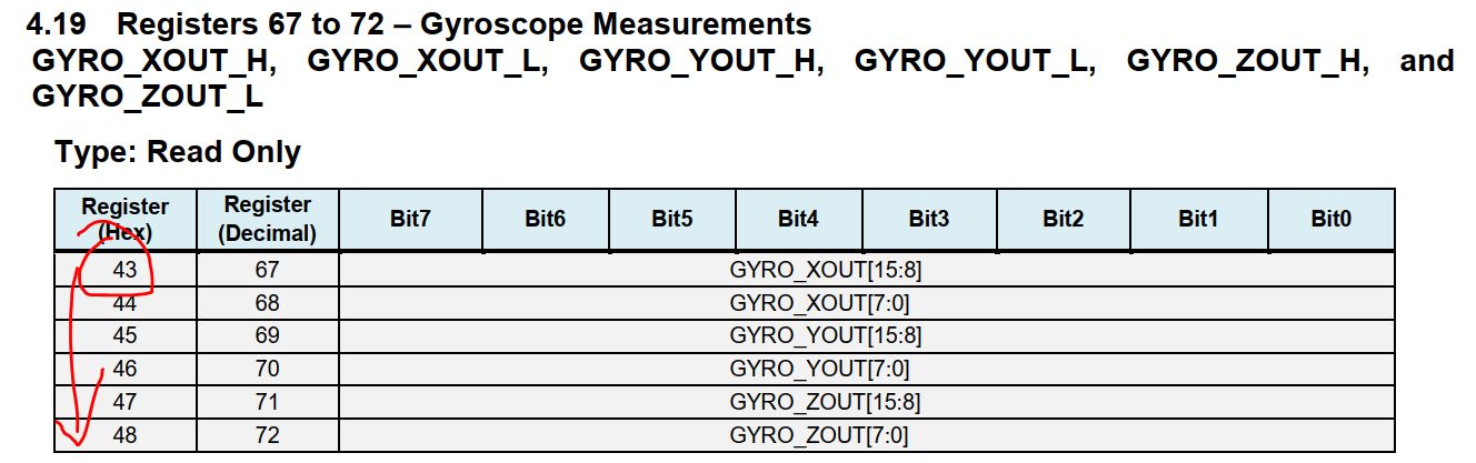
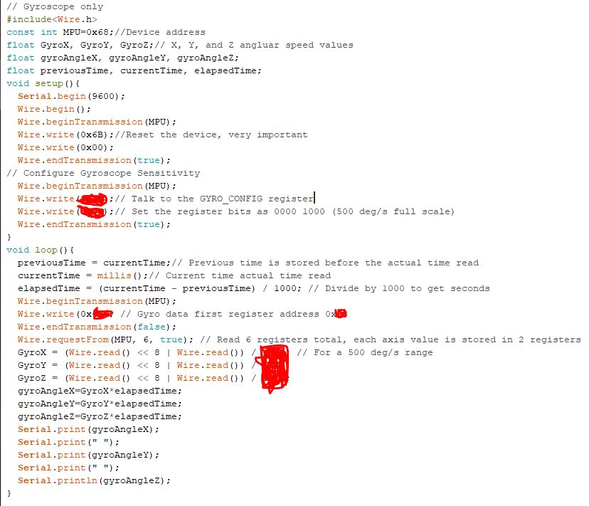
Download the data
sheet and the register
map of the MPU6050, make
register configuration (settings) accordingly before the data is being
collected.
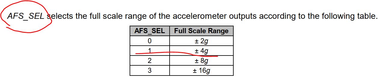
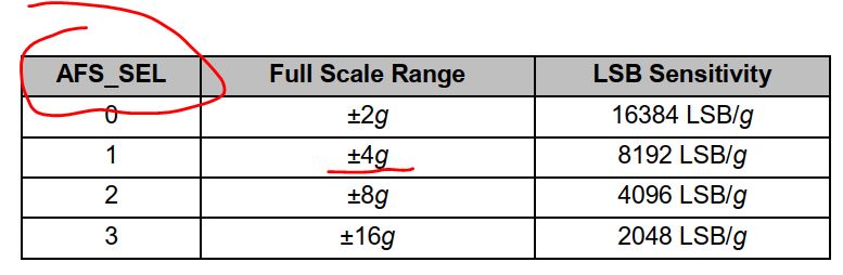
Define the range of the
accelerations that may be applied to the sensor. How many 'g'.
Must make according
configurations to translate the digital data into 'How Many g'.
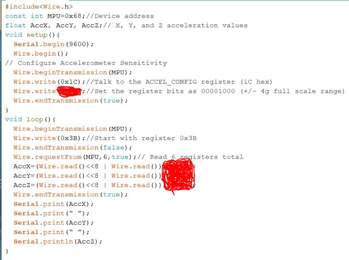
I masked the configuration
code for the ACCEL_CONFIG register and also masked the operation that
traslates the digital data into 'How Many g'.
Task
1:
Complete the hardware connection of your Arduino board
and the MPU6050. Complete the code above, run the program on your
Arduino and generate figures that show accelerations on the X, Y, and Z
axis separately. (three figures, X only, Y only, and Z only).
In the following video, I
mannually shaked my sensor at the X (blue), Y (red), and Z (green)
axises.
It uses
Micro-Electro-Mechanical Systems, or MEMS to implement the gyroscope
for angular speed measurement.
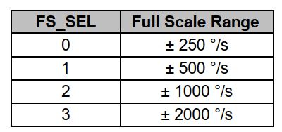
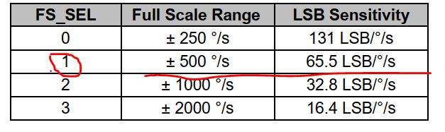
Configure the GYRO_CONFIG
register:
Pick up the possible range
for your specific application:
Task
2: Complete the code above, run the program on your
Arduino and generate figures that show angles on the X, Y, and Z
axis separately. (three figures, X only, Y only, and Z only).
My demonstration shows the X, Y, and Z angles at the same monitor at
the same time.
 ). It will
likely share a spot on the dial with one or more functions, usually
resistance (Ω). With the test probes separated, the multimeter’s
display may show OL and Ω.
). It will
likely share a spot on the dial with one or more functions, usually
resistance (Ω). With the test probes separated, the multimeter’s
display may show OL and Ω.