CE432 Fall 2022
Homework 9
Name: David Lee Email:
djlee1@fortlewis.edu
Two
Wheeled Balancing Car
Introduction:
The
Objective of this project is to get the Elegoo Tumbller balancing robot
to be able to drive around using a joystick. The joystick will be an
analog joystick connected to an Ardiuno uno that transmit data
wirelessly using a nRF24 to the Elegoo Tumbller robot which also has a
nRF24 on it.
Materials and Methods:
Elegoo Tumbller kit, Arduino uno, nRF24, Analog Joystick
Results:
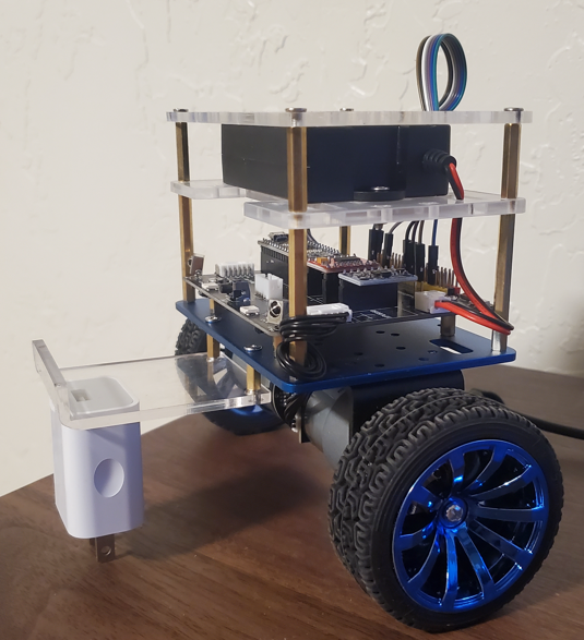
Task 1: Build the Robot
using the Kit
Figure 1: A picture of
the completed car Task
2: Simplify the code to have it
Balance, I2C integration, Forward,Backwards, Turning and Timer
Integration
Figure 2: Video of the car balancing
Figure 3: Video of the car Forward,
Backwards, Turning
For I2C integration I used
SPI similar to what we did in CE351, however I added the gyro calls to
the function. For the Timer integration I was able to find a reasource
on line that had a layout on how to implement it and I followed their
steps.
Task
3: Implement Joystick controlled
motion of the robot
Inorder to
implement the joystick controlled motion of the robot we need a way to
wirelessly communicate with the robot. We will use a nRF24 that is able
to recieve and transmit data. However the device connected to the robot
will only be recieving data while the other one connected to an Arduino
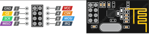
Uno will be transmitting the joystick data. Figure 4: Pin out of the nRF24
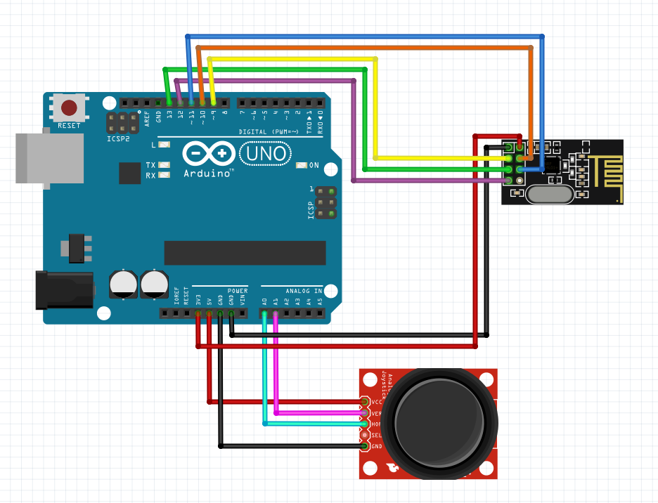
Figure 5: Connections between the
Joystick, nRF24 and Arduino Uno (Note: Colors in schematic match the
pinout for nRF24)
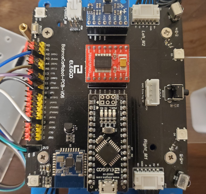
Figure 6: Connection between the
nRF24 and the Elegoo Tumbller Robot
Robot
Reciever
A3(Blue)
4
13(Brown)
7
11(Purple)
6
9(Black)
5
3(White)
3
3V3(Green)
2
GND(Grey)
1
Table
1: Connection guide for nRF24 to the Elegoo Tumbller Note: Table 1 references "Robot"
as pins in Figure 6 and
"Receiver" as pins in Figure 4.
It is important to remember
to remove the Ultra-Sonic Sensor in the front of the robot since it
uses some of these pins.
Now on to implementing the code for Task
3.
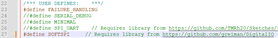
First modify library files in for the nRF24 to enable softSPI. Do you
this you need to open the RF24_config.h file in your favorite editor (I
use Notepad++). You'll need to uncomment the "define SOFTSPI" line in
my case it is line 27. You might also need to download an additional
library as seen in Figure 7.
Figure 7: Making Changes in Library
to enable SoftSPI
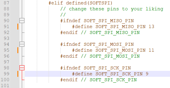
Next we need to adjust the pinouts
so that our Nano board knows which pins have been redefined, this is also in RF24_config.h. Refer to Figure 8.
Figure 8: Making Changes in Library
to redefine the pinouts
Each of these Files are throughly commented so you can understand what
is happening. The BalanceCar.h, and Pin.h were from the orginal
Tumbller code and were only slightly modified, which is why they are
not throughly commented.
Figure 9: A video of the joystick
controlled robot
The .ino and .h files can be found on the server at "CE432/HW9/TumbllerMain"
Discussion: This assignment was able to be
successfully completed. I was able to simplify the code the was
provided with the Elegoo Tumbller and include addition functions to the
robot. The posted code is well commented so anyone will be able to
understand what the function of the code is and why it needs to be
implemented. This project was both challenging and fun to complete. It
took me quite a while to figure out how to connect the nRF24 to the
Tumbller, but with a classmate giving me guidance I was able to figure
it out and get everything working. My Robot does not function as
smoothly as I would like while running the joystick controlled
sequence. So this would be able to be improved upon if I were to have more time to complete the project.