Lab 5 - A 3-bit Adder/Subtractor for 2's Complement Signed Binary Numbers
Name: Taylor Schermer
Email: tschermer@fortlewis.edu
Task 1:
1. Use switches as the 3-bit inputs, use 'leds' to show the binary
results. (30 points)
I have two modules: FullAdder and threeBitCalc, along with a testbench module threeBitCalc_TM. The FullAdder module implements the logic for a full adder, computing the sum and carry-out based on input bits a, b, and carry-in ci. The threeBitCalc module utilizes three FullAdder instances to perform addition or subtraction on three-bit binary numbers. It calculates the sum of the input bits a and b, incorporating a carry-in ci and generating sum outputs s0, s1, s2, and s3 and carry out vector c0 which is 3 bit. The value of the overflow is calculated by XORing c0[2] and c0[1]. If there is overflow it assigns the values for the addition or subtraction accordingly i.e. if overflow = 1 it sets the MSB to c0[2] or if overflow = 0 it sets the MSB to s2. Then tot is a four bit number with assign values based on the state of overflow. The threeBitCalc_TM testbench module simulates the functionality of the threeBitCalc module, connecting input switches to the a, b, and ci inputs and displaying the result through output LEDs.
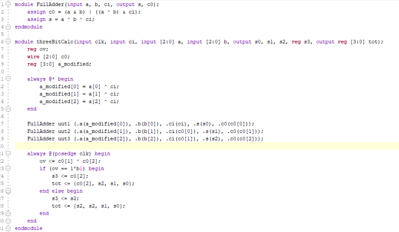
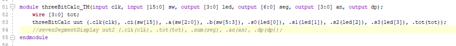
Figure 1. LED Binary Result Code
Task 2:
2.Use switches as the 3-bit inputs, use seven-segment displays to show the decimal result, make sure have the 'minus' sign in front of the decimal number if the result is negative. ( 30 points)
This task has the same functionality as above however it utilizes a Seven Segment Display with LEDs to display the results. The module sevenSegmentDisplay controls a ssd to show a the number represented by the input tot on each clock cycle. The module keeps track of its internal state using a two-bit state register state. It utilizes a counter cnt to synchronize the display updates with the clock signal clk. When cnt reaches the maximum count cntmax, the module updates the display according to the current state. In state 00, it determines whether the most significant digit of tot is nonzero. If so, it adjusts the display accordingly i.e whether the number is positive or negative. In state 01, it selects the appropriate seven-segment code for the digit based on the value stored in the digit register. The module cycles between these states to continuously update the display as the input tot changes.
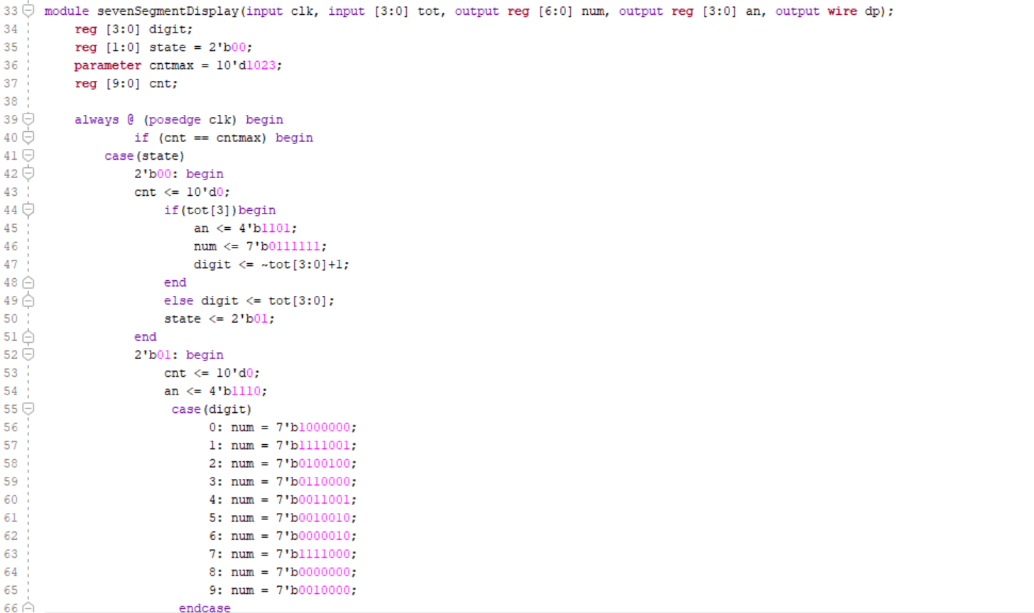
Figure 2. Seven Segment Display Binary Result Code
Task 3:
3. Use Serial In Parallel Out (SIPO) to input two 3-bit numbers [2:0] A, and [2:0] B, into the registers, then use one switch to trigger the computation. (40 points)
This task has the same functionality as above however it utilizes serial in parallel out with a Seven Segment Display and LEDs to display the results. The debounce debounces a button signal (btn) using a counter (count). It ensures that the button signal is stable for a specified duration (delay) before updating the debounced signal (btn_clr).The sipo module shifts the input serial data (si) into a shift register tmp on each rising edge of the push signal. It then outputs the parallel data (po) from the shift register. Then po is used in the threeBitCalc as the input.
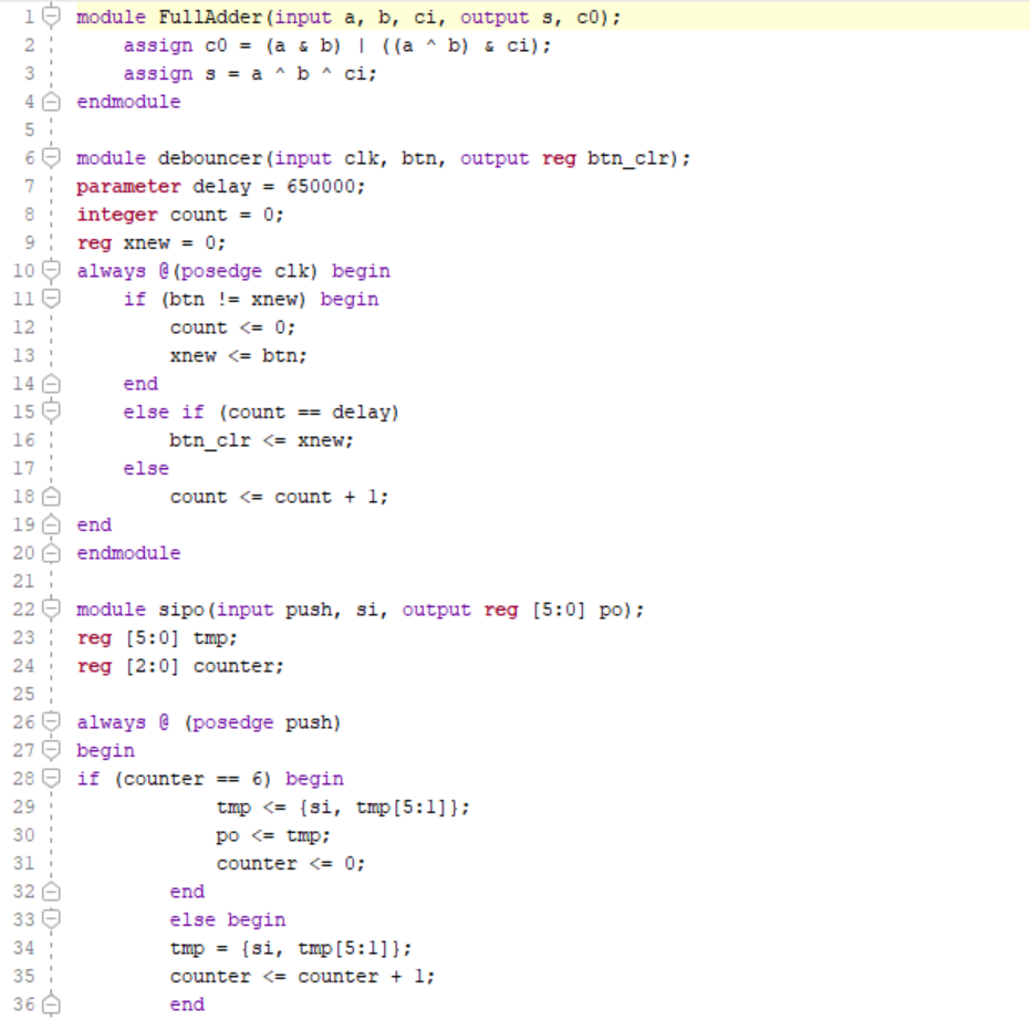
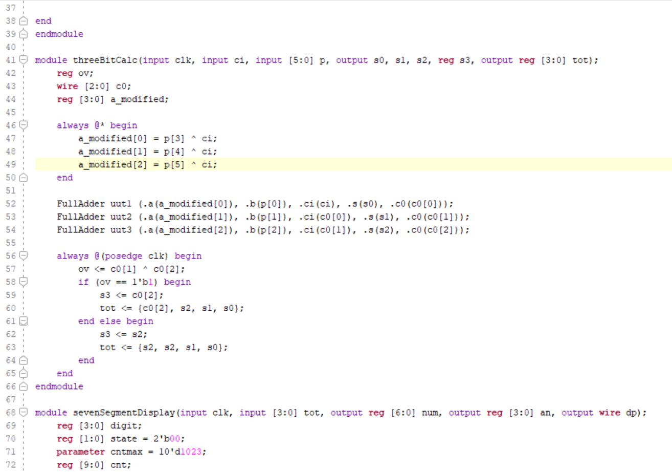
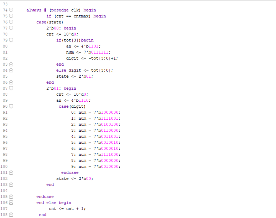
Figure 3. SIPO Binary Adder and Subtractor Result Code