Lab 4 - Combinational Logic Blocks
Name: Taylor Schermer
Email: tschermer@fortlewis.edu
Task 1:
1. Think about how many states the two-way traffic lights may have for
each cycle. The green light on one side turns yellow and then turns red
before the other light changes to green from red. Draw the truth table
for all the states in one cycle of the traffic light change. Simplify
the logic equations for each light using the K map. Design the Verilog
model and the testbench, show the simulation results in Vivado. Use 6
leds on your Basys 3 board to implement the design. Show the demo video
for credits. (50 points)
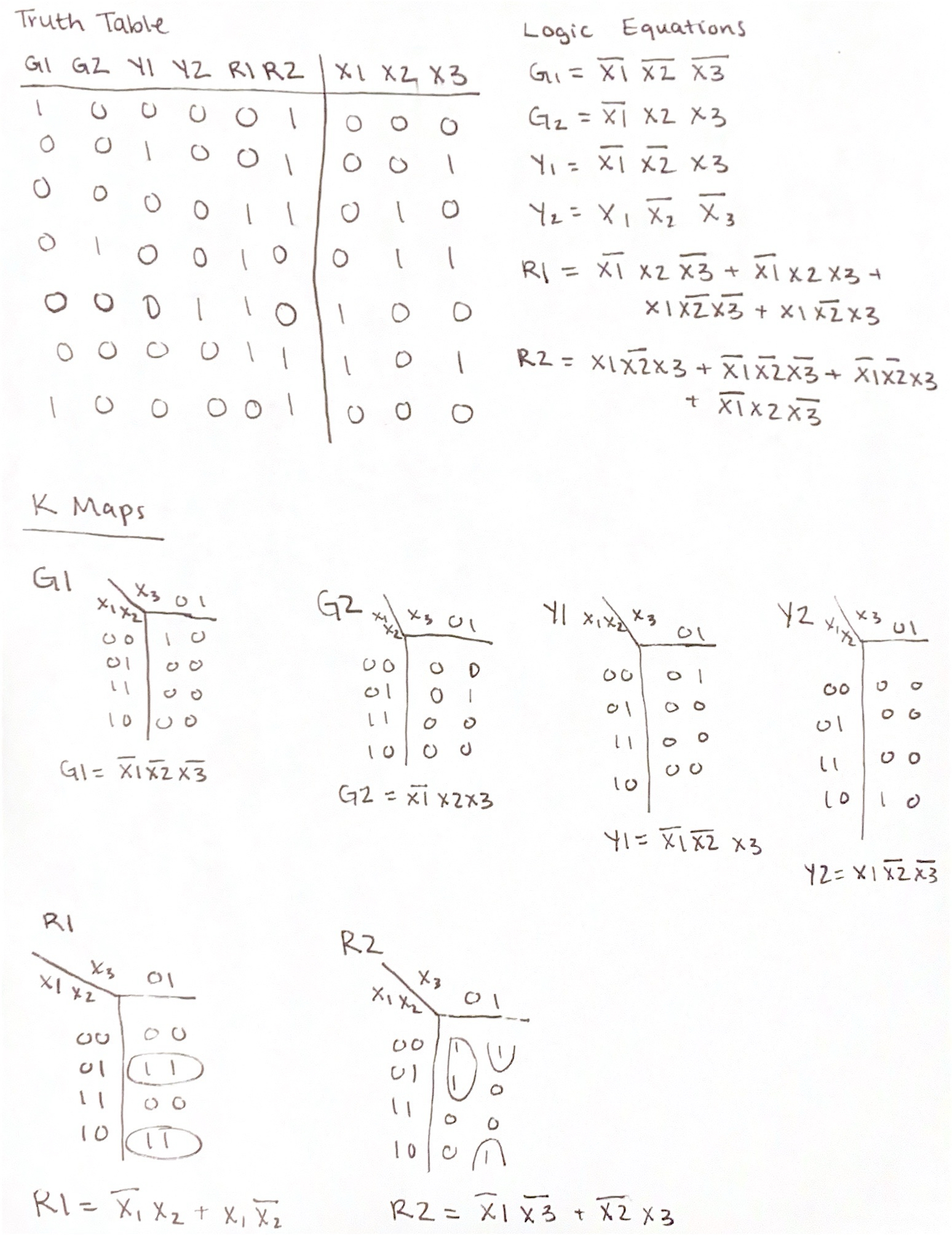
Figure 1. Truth Table, Logic Equations, and K Map
The twoWayTrafficSim module simulates a two-way traffic signal system. It has three input signals x1, x2, and x3, which represent the states of sensors or traffic detectors. It also has six output signals g1, g2, y1, y2, r1, and r2, representing the states of the traffic lights. The logic inside the twoWayTrafficSim module determines the state of each traffic light based on the combination of input signals. For example, g1 and g2 are green lights for the two different directions of traffic flow, y1 and y2 are yellow lights, and r1 and r2 are red lights. The twoWayTrafficLight_tb module serves as a testbench for the twoWayTrafficSim module. It initializes the input signals x1, x2, and x3, simulates changes in their values, and observes the corresponding output signals g1, g2, y1, y2, r1, and r2, allowing for testing of the two-way traffic signal system.
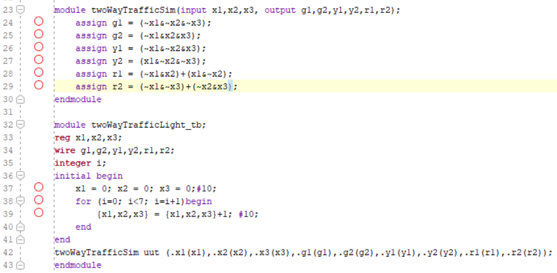
Figure 2. Two Way Traffic Light Logic Code
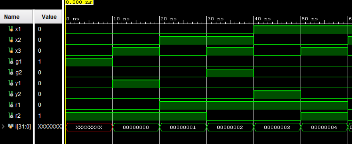
Figure 3. Two Way Traffic Light Logic Simulation
The twoWayTrafficLight module represents a two-way traffic light system. It takes a clock input clk and generates outputs g1, g2, y1, y2, r1, and r2 representing the states of the traffic lights. The module simulates the operation of traffic lights with different states. It utilizes a counter cnt to control the timing of state transitions and it transitions between different states based on the current state and the value of the rush hour input. In each state, the module sets the output signals g1, g2, y1, y2, r1, and r2 accordingly to control the behavior of the traffic lights.
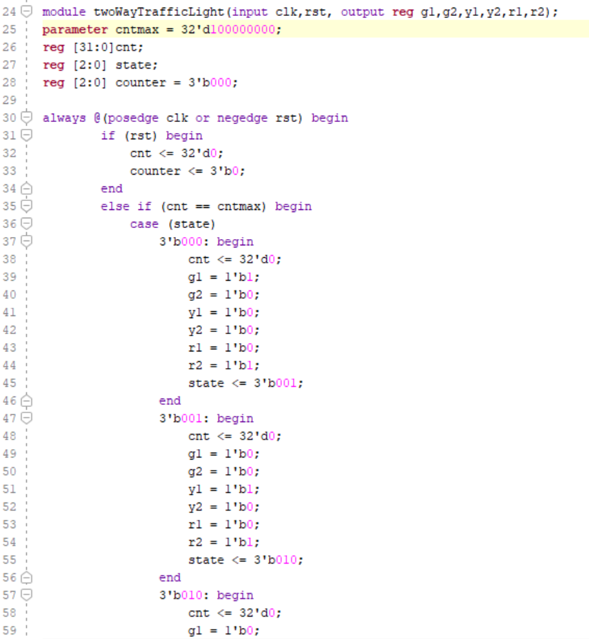
Figure 4. Running Two Way Traffic Light Code Part 1
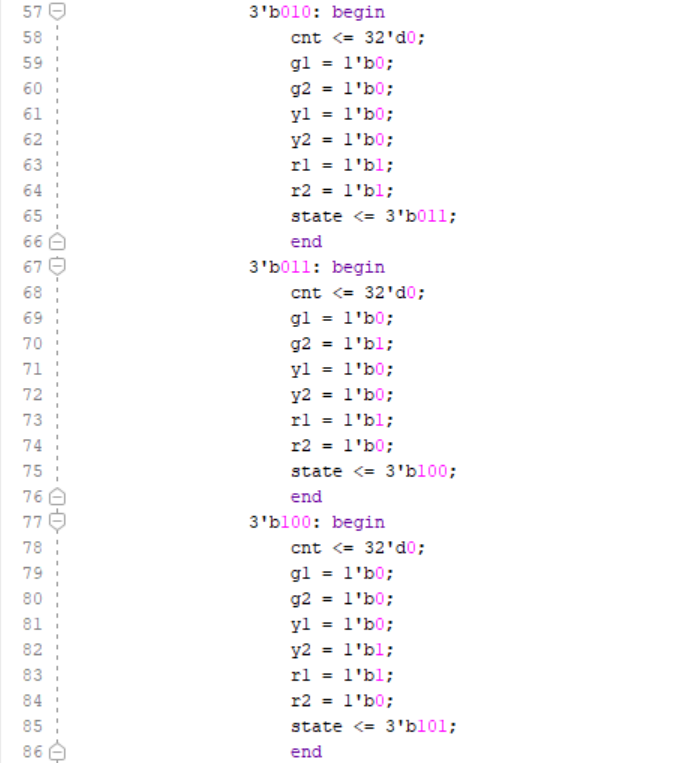
Figure 5. Running Two Way Traffic Light Code Part 2
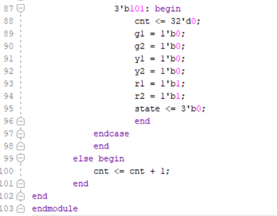
Figure 6. Running Two Way Traffic Light Code Part 2
Task 2:
2. While the first problem cycles through all states with the same durations, during rush hours, the busy road has a longer duration for the green light than the red light. Use a switch to trigger the rush hour mode, which keeps one of the green lights ON for double the duration compared to the other road. Show the code, code explanation, and demo video in your report. ( 50 points)
This module works the same as the one from Task 1, but it includes a rush hour setting. When a switch is set high, one of the green lights is on for twice as long.
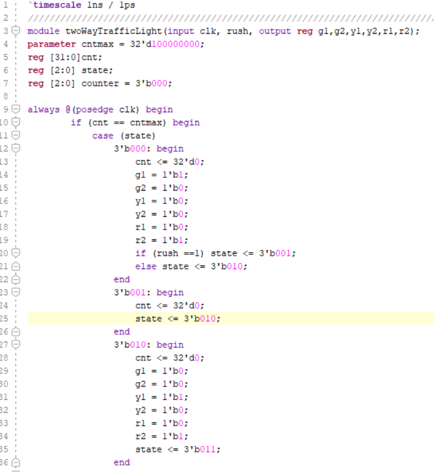
Figure 7. Rush Hour Running Two Way Traffic Light Code Part 1
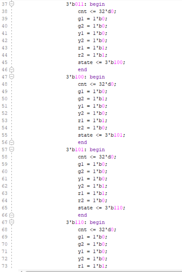
Figure 8. Rush Hour Running Two Way Traffic Light Code Part 2
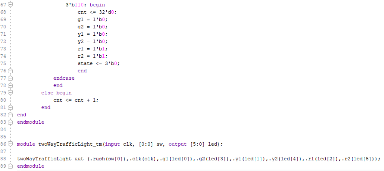
Figure 9. Rush Hour Running Two Way Traffic Light Code Part 3