Lab 3 - Seven-Segment Display on An FPGA Part 1
Name: Taylor Schermer
Email: tschermer@fortlewis.edu
Task 1:
1. Complete the tasks in Sections
1. Show your code, explanation, and demonstrate it in an embedded video.
(20 points)
Inverter:
This inverter module takes an input signal x and outputs its logical negation y. The topmodule connects the input of the inverter to a single-bit input switch and its output to a single-bit output led. There's also a commented-out testbench (invertor_tb) for simulating the inverter module's functionality.
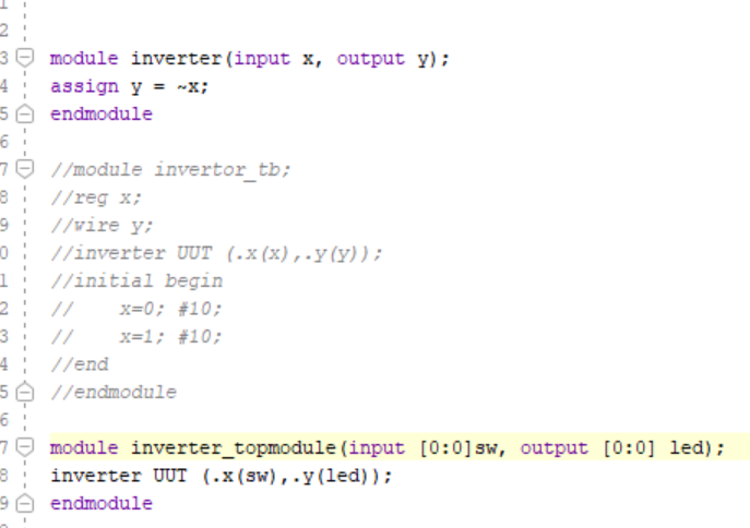
Figure 1. Inverter Code
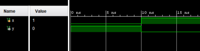
Figure 2. Inverter Sim
Two bit Full Adder:
The full adder logic is implemented in the FullAdder module. The TwoBitFullAdder module utilizes two instances of the FullAdder module to perform addition on 2-bit inputs a and b, with a carry-in c_i, producing a 2-bit sum s and a carry-out c_0. The testbench (TwoBitFullAdder_TB) is for simulating the functionality of the 2-bit full adder.
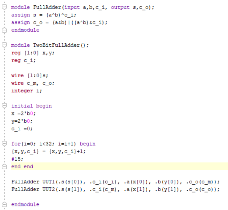
Figure 3. Two Bit Adder Code
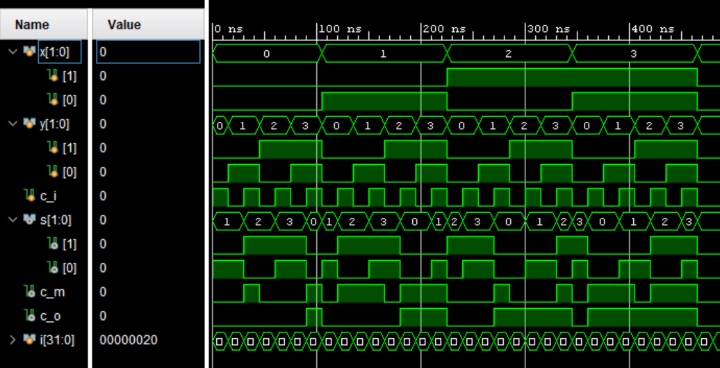
Figure 4. Two Bit Adder Sim
The top-level module connects switches to the inputs a, b, and c_i, and connects the output LEDs to display the sum and carry-out.
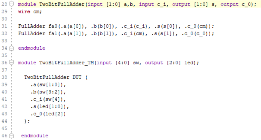
Figure 5. Two Bit Adder Test Module Code
Eight Bit AND Gate:
This module (eightBitAnd) performs a bitwise AND operation on eight input bits (a through h) and produces a single output y. The logic is straightforward, where the output y is the result of performing AND operation on all input bits. The testbench (eightBitAnd_TB) is for simulating the functionality of the eight-bit AND module.
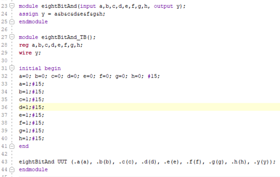
Figure 6. Eight Bit AND Gate Code
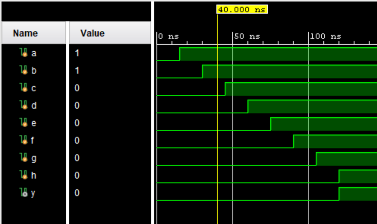
Figure 7. Eight Bit AND Gate Sim
There's a top-level module (eightBitAnd_TM) that connects switches to the inputs a through h and connects the output LED to display the result of the AND operation
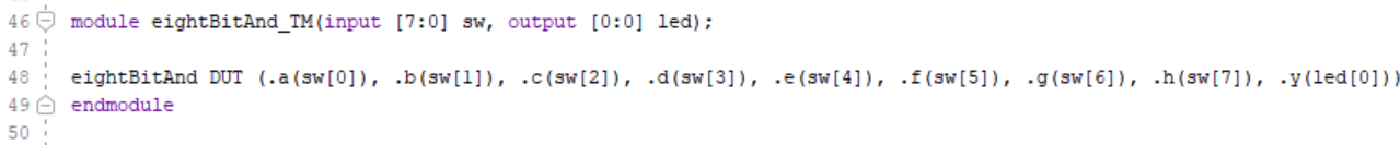
Figure 8. Eight Bit AND Gate Test Module Code>
4:1 MUX:
This module (fourMUX) for implements a 4-to-1 multiplexer with four input signals (a, b, c, d), two select lines (s0, s1), and one output y. The output y is determined based on the select lines: if s1 is high, the output is either c or d, depending on the state of s0; otherwise, the output is either a or b, again depending on the state of s0. The testbench (fourMUX_TB) is for simulating the functionality of the 4-to-1 MUX module.
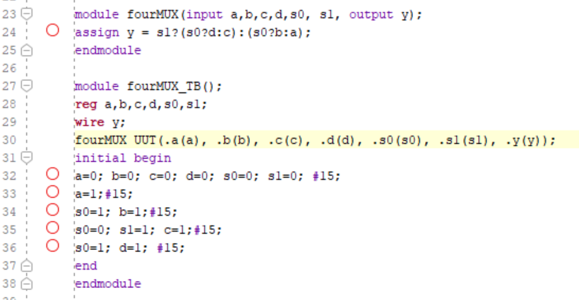
Figure 9. 4:1 MUX Code
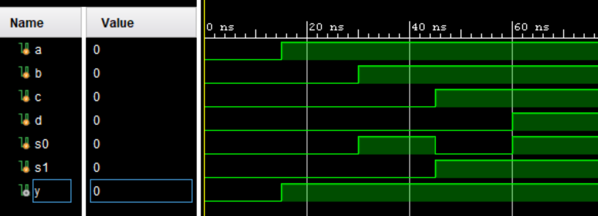
Figure 10. 4:1 MUX Sim
There's a top-level module (fourMUX_TM) that connects switches to the inputs and select lines of the MUX and connects the output LED to display the selected signal.

Figure 11. 4:1 MUX Test Module Code
Task 2:
2. Complete the tasks in Section 2. Show your code, explanation, and demonstrate it in an embedded video. (20 points)
This module (runningLED) creates a running LED effect using a clock signal (clk) and a reset signal (rst). The LED pattern shifts cyclically, creating a running effect. The cnt register is used to control the speed of the running effect.. Upon reset (rst), the counter (cnt) is reset, and the LED pattern starts with the rightmost LED illuminated. As the counter reaches its maximum value (cntmax), the LED pattern shifts one position to the left. The top-level module (runningLED_TM) instantiates the runningLED module, connecting clock, reset, and LED output signals accordingly.
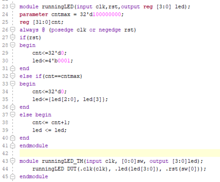
Figure 12. Running LED Code
Task 3:
3. Similar to the example in Section 2, show running LEDs on all 16 LEDs. Show your code, explanation, and demonstrate it in an embedded video. (20 points)
The code works the same as in section two but instead of using [3:0] leds we use [15:0] leds.
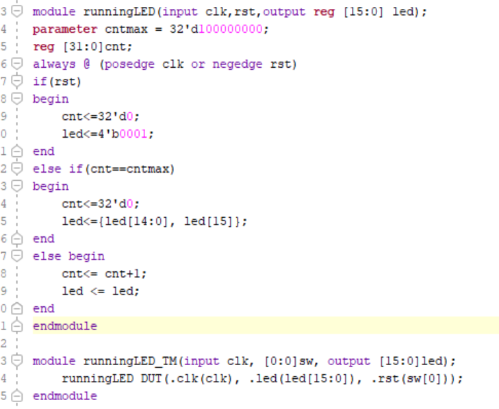
Figure 12. 16 Running LEDs Code
Task 4:
4. Similar to the example in Section 2, change the frequency of the 4 running LEDs to half second and demonstrate it in an embedded video. (20 points)
Agian, the code works the same as in section two but the value of cntmax is divided by 2 so the leds blink twice as fast.
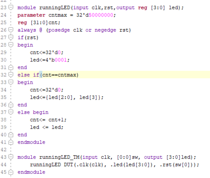
Figure 13. Running LEDs in 2x Speed Code
Task 5:
5. Complete the task in Section 3. Show your code, explanation, and demonstrate it in an embedded video. (20 points)
This module (sevenSegmentDisplay) controls a seven-segment display. It takes inputs including a clock signal (clk) and a 4-bit binary input value (x). Inside the module, there's a case statement that maps each input digit to the corresponding segments to be illuminated on the display. The top-level module (sevenSegmentDisplay_TM) instantiates the sevenSegmentDisplay module, connecting clock, input values, and display output signals accordingly.
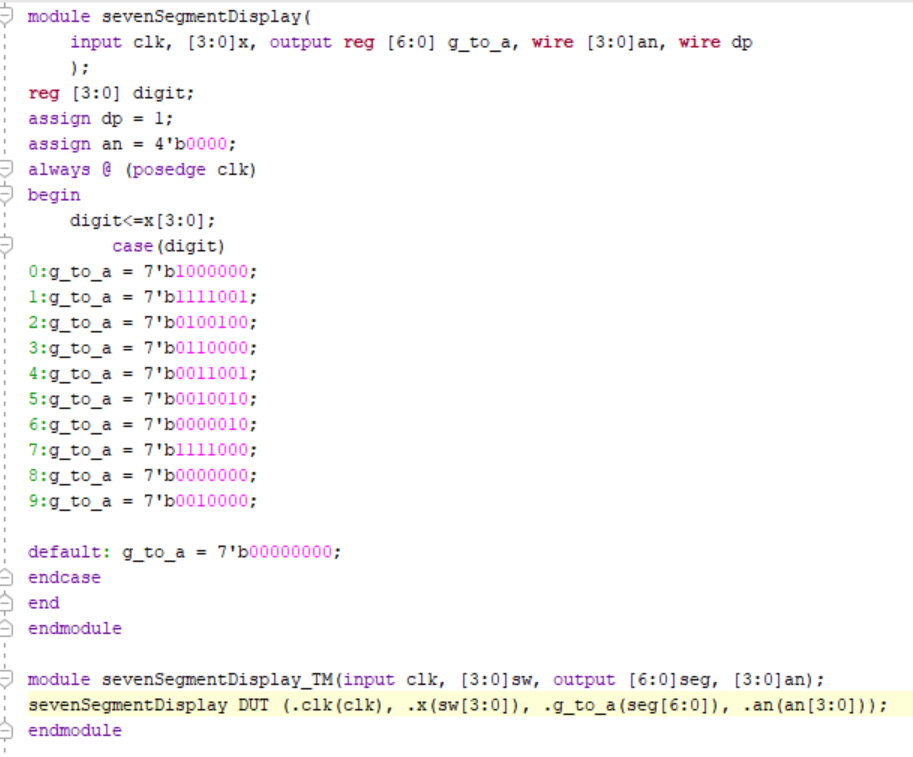
Figure 14. Running LEDs in 2x Speed Code
Week 2:
Task 1:
1. Complete the task in Section 4. Show your code, explanation, and demonstrate it in an embedded video. (30 points)
This module works exactly like the sevenSegmentDisplay module. It controls a seven-segment display and takes inputs including a clock signal (clk) and a 4-bit binary input value (x) and outputs the decimal number on one of the 4 seven segment displays.
Figure 15. Change in Seven Segment Display Code
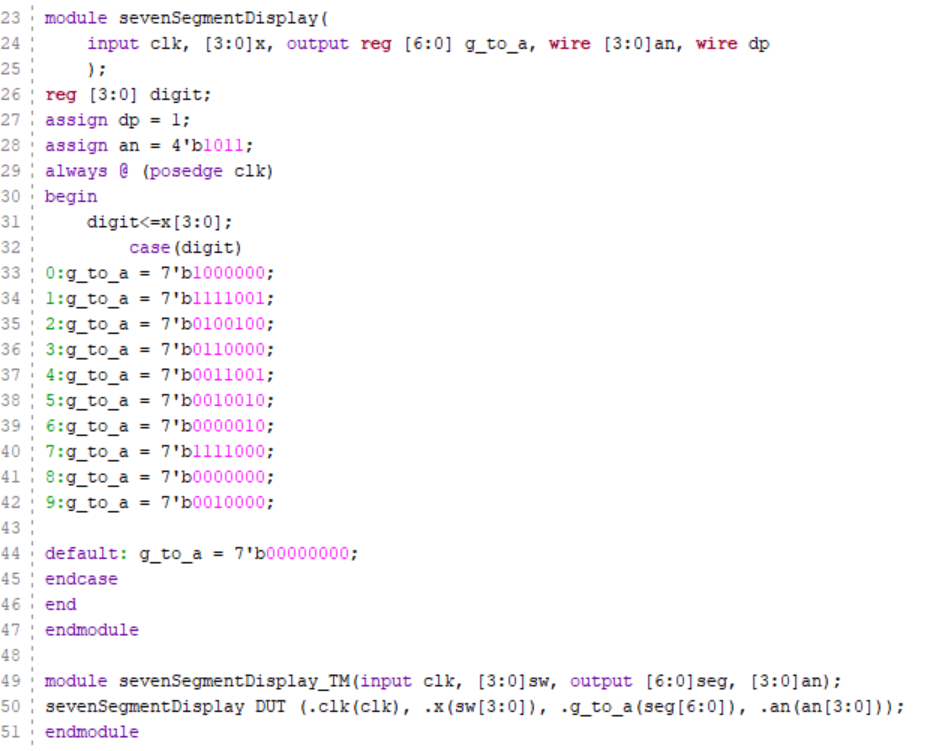
Figure 16. Seven Segment Display Code
Task 2:
2. Show "FLC" on three of the display units. Show your code, explanation, and demonstrate it in an embedded video. (30 points)
The module FLCSSD controls a 7-segment display to display FLC. It uses a clock input (clk) to synchronize operations. It cycles through three states, each representing a different digit to be displayed on the 7-segment display. The cnt variable is used as a counter to determine when to transition to the next state. When the counter reaches the maximum count (cntmax), it resets and advances to the next state, updating the display accordingly. It loops fast enough that to the human eye it appears stagnant. The module FLCSSD_TM instantiates FLCSSD and connects its inputs and outputs appropriately.
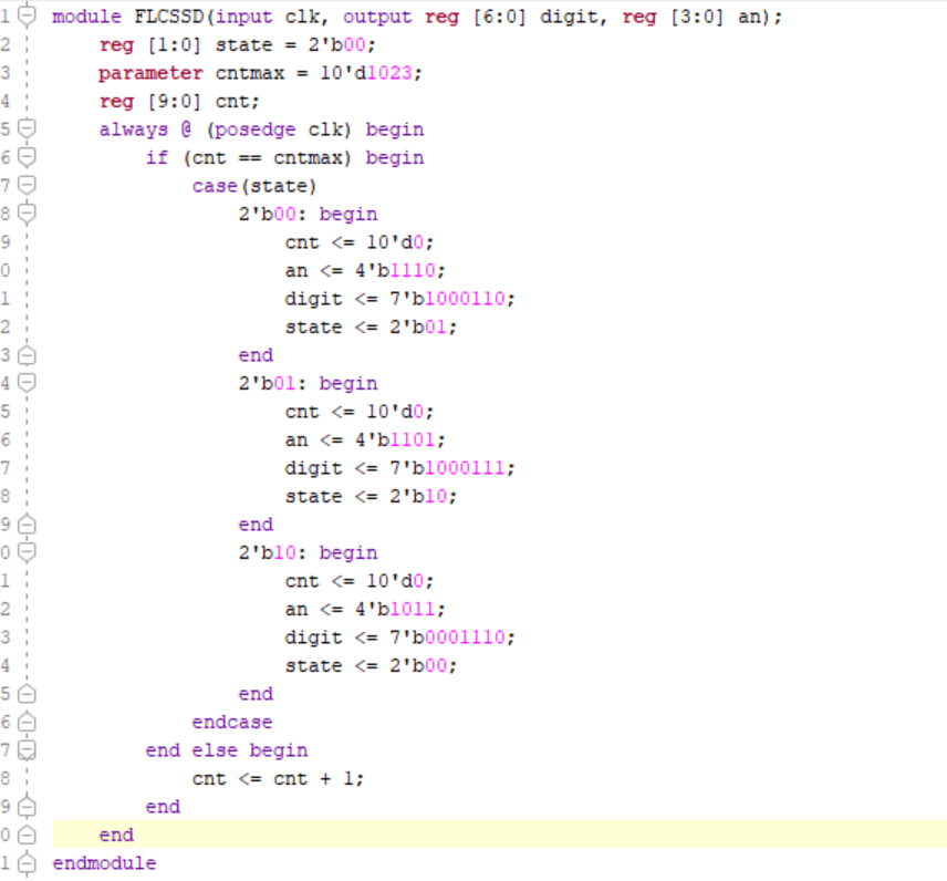
Figure 17. FLC Seven Segment Display Code
Task 3:
3. Roll "FLC" to the left for every half second. After "F" shifted out to the left, it should appear on the right hand side. Show your code, explanation, and demonstrate it in an embedded video. (40 points)
the FLCSSDRoll module drives a seven-segment display to simulate a rolling FLC pattern. It utilizes two counters (cnt and cnt2) to control the speed of the rolling pattern. The state variable keeps track of the current state of the module, determining which segment pattern to display. The module continuously updates the segment pattern based on the state and increments the counters to control the rolling speed. The FLCSSD_TM module serves as a test module for the FLCSSDRoll module. It connects the clock input (clk) to the module, and the output seven-segment display (seg) and anode control (an) to display the rolling pattern on a physical display.

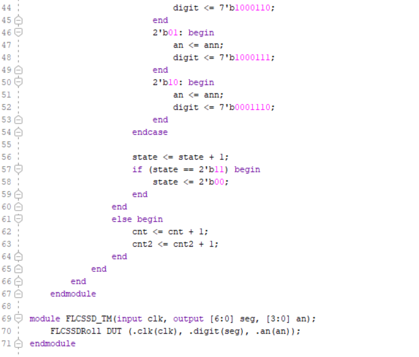
Figure 17. FLC Rolling Seven Segment Display Code