Homework 2 - Data Types, Operators, Combinational Logic
Name: Taylor Schermer
Email: tschermer@fortlewis.edu
Task 1:
1. Work on the following problems:
(20 points)
a. What are the fixed point
representations of the following decimal numbers? Display your
calculations and results on a paper and take a picture of it as an
embedded image on your website.
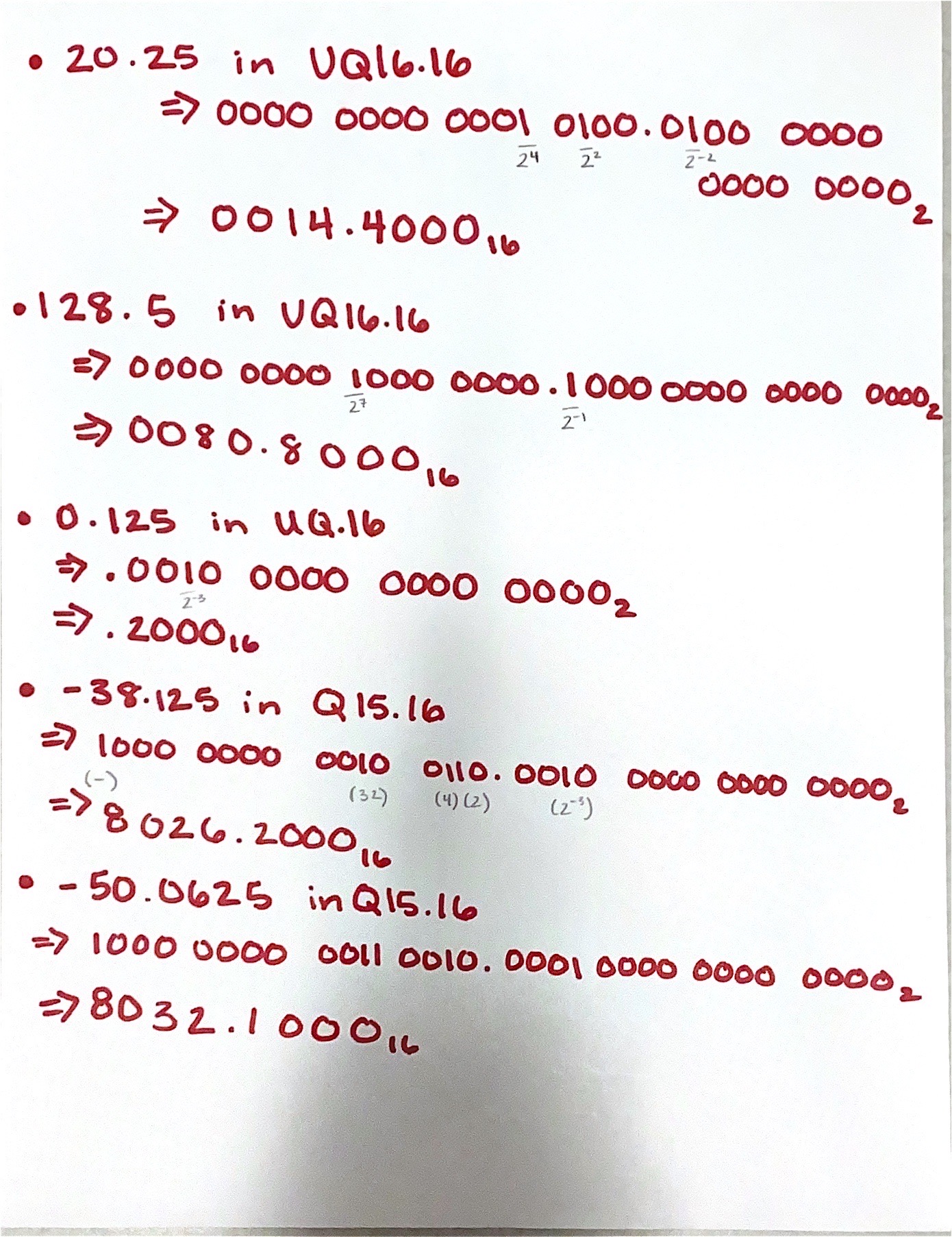
Figure 1. Fixed Point Representations
b. What are the floating point
representations of the following decimal numbers? Display your
calculations and results on a paper and take a picture of it as an
embedded image on your website.
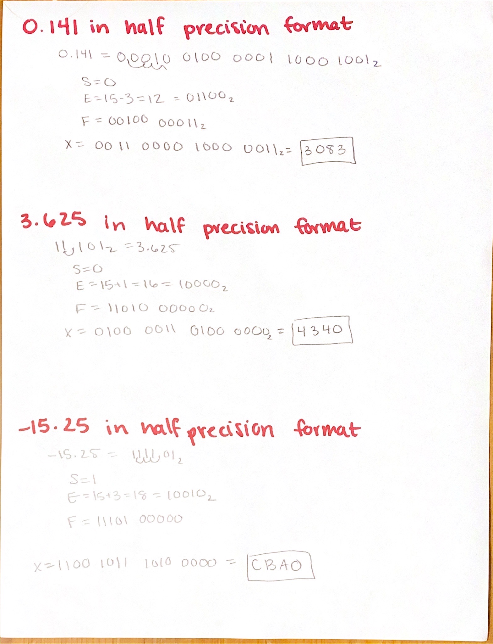
Figure 2. Floating Point Representations
Fixed point representation involves a set number of bits for the integer and fractional parts of a number, maintaining a fixed position for the decimal point throughout calculations. Floating point representation, on the other hand, adjusts the position of the decimal point based on the magnitude of the number. This allows for a wider range of values but can result in less precision for very small or very large numbers.
Task 2:
2. Repeat the simulation work in
Section 5. Demonstrate your results in embedded videos on your website.
(20 points)
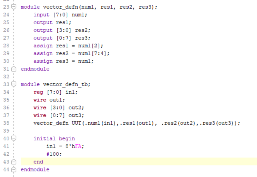
Figure 3. Problem 2 Code
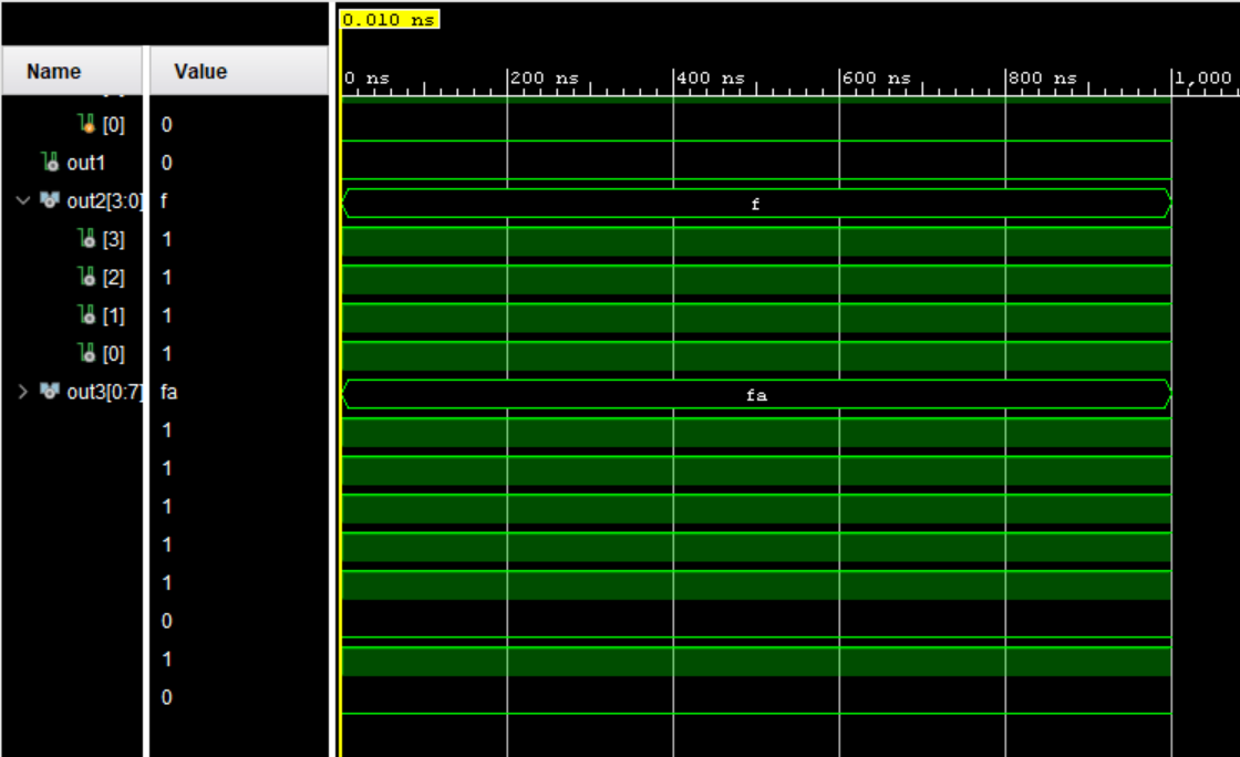
Figure 4. Problem 2 Simulation
This code defines a module called "vector_defn" that takes an 8-bit input "num1" and splits it into three parts: "res1" which is one bit, "res2" which is 4-bits, and "res3" which is the original 8-bit vector. "res1" takes the third bit of "num1" and "res2" takes the upper four bits of "num1". The "vector_defn_tb" module is a testbench for "vector_defn". It initializes an 8-bit register "in1" with the value 0xFA (11111010) and connects it to "num1" input of "vector_defn". The outputs "out1", "out2", and "out3" are declared as wires.
Task 3:
3. Repeat all the FPGA experiments in Section 7. Demonstrate your results in embedded videos on your website. (30 points)
Home Alarm System:

Figure 5. Home Alarm System Code
This module takes two inputs: "s", a 4-bit vector representing sensors, and "m", a single bit representing whether the system's armed or disarmed. The output "a" indicates whether the alarm system is on or not. The alarm is activated if any of the sensors are triggered (at least one in "s" is 1) and the system is armed ("m" is 1). The "homeAlarmSystem_tb" module is a testbench for "homeAlarmSystem". It connects the switches "sw" (a 5-bit vector) to simulate sensor inputs and if the system is armed. The LED "led" displays if the alarm goes off. It instantiates the "homeAlarmSystem" module, connecting its inputs and outputs accordingly, and facilitates the alarm system.
Digital Safe System:
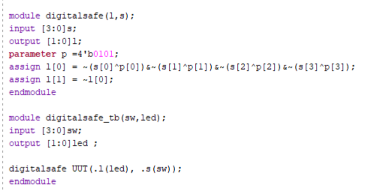
Figure 6. Digital Safe Code
This module defines a digital safe system named "digitalsafe". It takes a 4-bit input "s" representing the user's input and produces a 2-bit output "l" indicating whether the input matches a predefined passcode. The passcode is defined as "p" with the value 0101. l[0] is set to 1 if the input matches the passcode, and l[1] is set to one if the passcode doesnot match. The "digitalsafe_tb" module serves as a testbench for the "digitalsafe" module. It connects the switches "sw" (a 4-bit vector) to simulate user input and the LED "led" (a 2-bit vector) to display the output of the digital safe. It instantiates the "digitalsafe" module, connecting its inputs and outputs accordingly, and facilitates the safe system.
Parking Spot Count System:
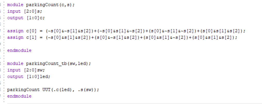
Figure 6. Parking Count System Code
This module simulates a parking space occupancy counter. It takes a 3-bit input "s" representing the status of three parking spaces (0 for empty, 1 for occupied) and produces a 2-bit output "c" representing the count occupied spaces in binary. The "parkingCount_tb" module serves as a testbench for the "parkingCount" module. It connects the switches "sw" (a 3-bit vector) to simulate parking space statuses and the LED "led" (a 2-bit vector) to display the count of occupied parking spaces in binary. It instantiates the "parkingCount" module, connecting its inputs and outputs accordingly, and facilitates the parking system.
Task 4:
4. Design a simple digital system
using the similar combinational logic design methods shown in Section 7.
Explain what the system is, show the design files, demonstrate it on
your FPGA. Demonstrate your results in embedded videos on your website.
(30 points)
Decimal to Binary Counting System:
My moduele converts a 16-bit
decimal input "s" into a 4-bit binary output "l", where each bit of "l"
represents a power of two in the binary representation of the input
decimal number from the switch. "l[0]" represents the least significant
bit (LSB) of the binary number and is assigned based on the odd-numbered
bits of "s". "l[1]" represents the next bit of the binary number and is
assigned based on specific combinations of bits in "s". This pattern
continues for "l[2]" and "l[3]", representing higher-order bits of the
binary number. The "DecimalToBinary_tb" module serves as a testbench for
the "DecimalToBinary" module. It connects the switches "sw" (a 16-bit
vector) to simulate decimal inputs and the LED "led" (a 4-bit vector) to
display the binary output. The system is not designed for more than one
switch to be on at a time. Further development can be done by
incorporating logic to ensure that if multiple switches are activated,
no LEDs are lit.
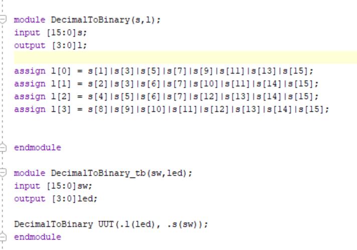
Figure 7. Decimal to Binary System Code