Task 1: Assemble the car
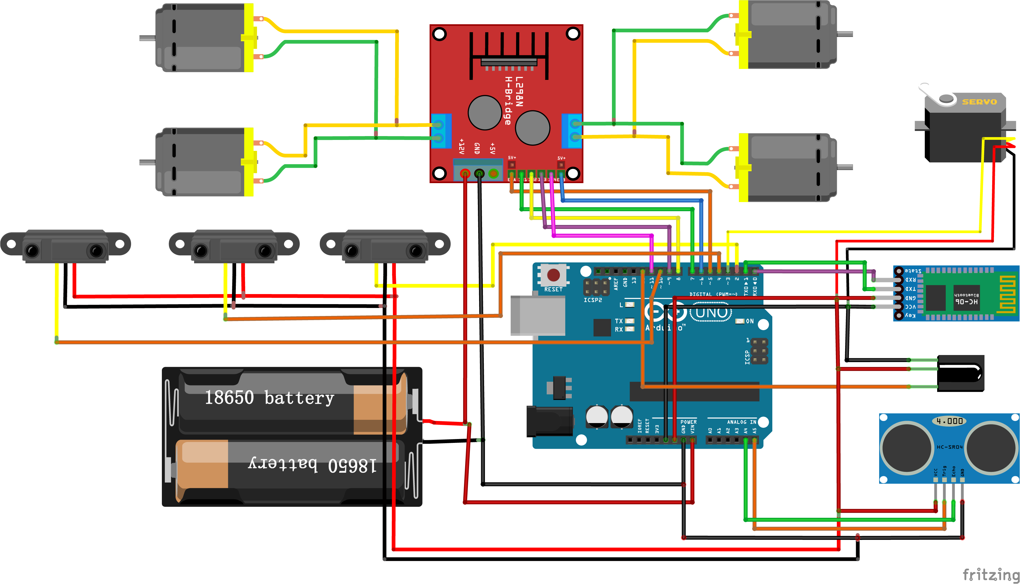
Figure 01: Smart Car Fritzing Wiring Diagram
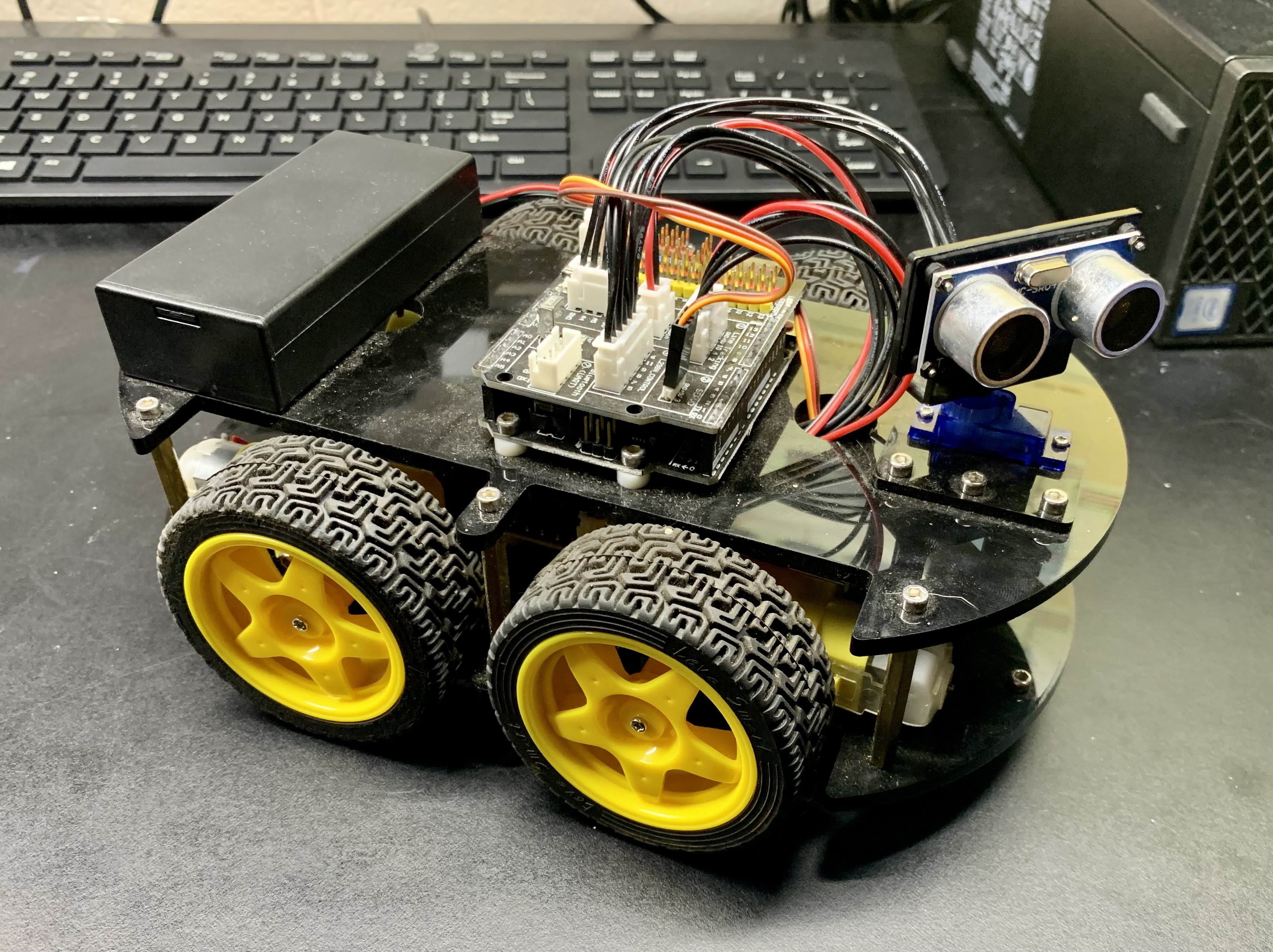
Car was already assembled by a previous class so I didn't have to do task 1.
| Materials | Quantity |
| Arduino Uno R3 |
1 |
| HC-SR04 sensor |
1 |
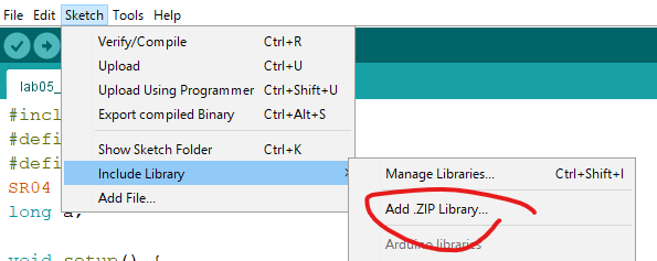
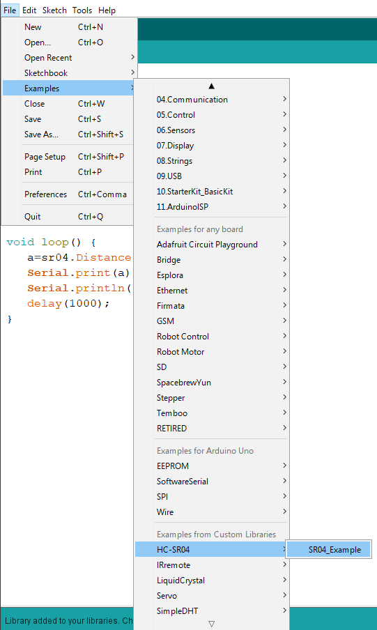
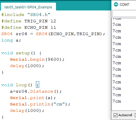
#include "SR04.h"Figure 06: SR04_Example code from the HC-SR04 library
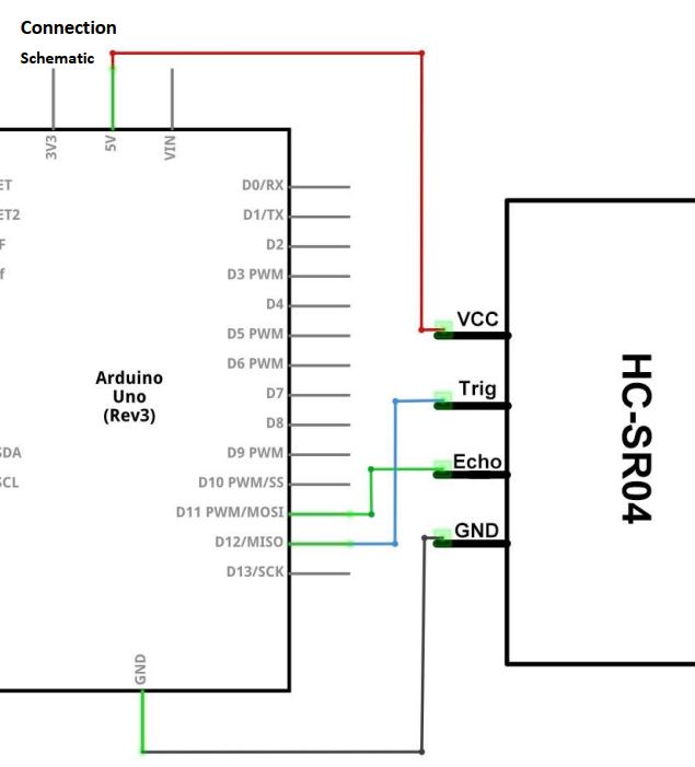
#define TRIG_PIN 12
#define ECHO_PIN 11
SR04 sr04 = SR04(ECHO_PIN,TRIG_PIN);
long a;
void setup() {
Serial.begin(9600);
delay(1000);
}
void loop() {
a=sr04.Distance();
Serial.print(a);
Serial.println("cm");
delay(1000);
}