CE351 Lab 2023 Spring
Lab 4 - PID Control - Photocell
Name: Simon Gorman
Email: sbgorman@fortlewis.edu

1. PID Control - Photocell

2. Introduction
Tasked with putting together a simple PID control setup with a photocell and LEDs where the ambient light was recorded into the Arduino Serial Plotter. We added LEDs and calculated the setpoint for the light oscillations.

3. Materials and Methods
Materials Quantity
Arduino Elegoo Uno R3 1
Breadboard 1
Jumper wires 20
Photocell 1
LEDs 2
1k Resistor 1
200 to 1k Resistor
1
2k to 10k Resistor
1

Started by using the following schematic (see Fig. 01) to connect my photocell to the breadboard and Arduino Uno (see Fig. 02):
photocell schematic
Figure 01: Photocell and LED schematic to the Arduino Uno

Initial Testing - Wiring Diagram of a Photocell and one LED
Figure 02: Wiring diagram of the Photocell, LED, and Arduino Uno

Initial Testing - Test the current ambient light intensity
Initial testing of the Photocell and Arduino coding in the microcontroller lab room with  no LED (see Fig. 03):

Photocell readings of only the ambient lighting
Figure 03: Arduino code and Arduino Serial Monitor of the Photocell readings of only the microcontroller lab room lighting

Initial testing of the Photocell and Arduino coding in the microcontroller lab room with the white LED:

Photocell readings of the ambient lighting and the white LED
Figure 04: Arduino code and Arduino Serial Monitor of the Photocell readings of the microcontroller lab room lighting and the white LED

The serial readings from the photocell are slightly off due to the time delay between the execution of the 'analogRead' function and the read to the CPU. The current code is not producing the real value so we added a time delay of 1 second after the 'digitalWrite()' function (see Fig.05):

Added 1 second time delay to Arduino code
Figure 05: Arduino PID code with 1 second time delay after 'digitalWrite()' function


Recorded the light intensities with the modified code and these (see Table 01) are the current values:

Light Source Light Intensity
Ambient lighting (Microcontroller lab) 206
Ambient lighting and the white LED 798
Table 01: Table of Light Intensities after adding the 1 second time delay

To find the SetPoint (SP), I calculated the median between the ambient light intensity, 206, and the brightest light intensity, 798, which is 502.

I ran the following Arduino code (see Fig. 06):
Arduino Serial Plotter oscillating around 502
Figure 06: Arduino Serial Plotter with the plot oscillating around 502

The plot exceeded my ambient light intensity of 206 by oscillating around 502 which means the system will never reach the setpoint so I had to modify the code again.

Task 1 - Fixed the code so the sensed light oscillates around the setpoint

Added an extra LED to change the ambient light then added a pushbutton to turn on/off the LED

Photocell, extra LEDs, and a pushbutton circuit diagram
Figure 07: Schematic for photocell with additional LEDs and a pushbutton

wiring diagram of photocell, two LEDs, and pushbutton
Figure 08: Wiring diagram of the Photocell, two LEDs, pushbutton, and Arduino Uno

Task 2 - Save Data in a Local Drive and Plot Data on Python

Python pidPhotocell code
Figure 09: Python code for plotting the pidPhotoCell

Ambient Lighting Plotted with Python
Figure 10: Graph of PhotoCell Resistor Plotted with Python

Edited the python code in Fig.09 to plot the data collected while pressing the pushbutton and it plotted Fig.11
python plotter -- pidPhotoCell with pushbutton
Figure 11: Graph of PhotoCell Resistor and pushbutton Plotted with Python

Task 3 - Fixed the setPointChange() function
 
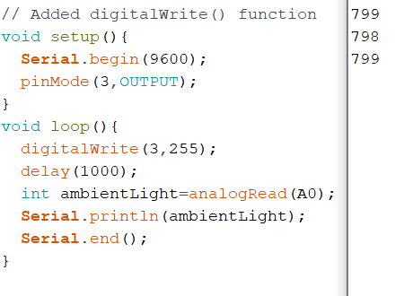
Arduino code for the fixing the setPointChange() function:

// Test 3: Photocell PID with setPoint variable
float Kp=0.1, Ki=0, Kd=0;
float error=0, previous_error=0;
float P=0, I=0, D=0;
float PID_value=0;
int setPoint=502;
float initialValue=10;
int buttonState;
int lastButtonState;
void setup() {
 pinMode(3,OUTPUT);
 pinMode(4,INPUT);
 analogWrite(3,initialValue);
 Serial.begin(9600);
}
void loop() {
 setPointChange();
 int photoSignal=analogRead(A0);
 error=setPoint-photoSignal;
 P=error;
 I+=error;
 D=error-previous_error;
 previous_error=error;
 PID_value=PID_value+Kp*P+Ki*I+Kd*D;
 analogWrite(3,PID_value);
 Serial.print(setPoint);
 Serial.print(", ");
 Serial.println(photoSignal);
}

void setPointChange(){ // state detection (edge detection) works.
 buttonState=digitalRead(7);
 if (buttonState!=lastButtonState){
   delay(10);
   if (buttonState==HIGH){
     if (setPoint<900){
       setPoint+=20;
     }
   }
 }
 lastButtonState=buttonState;
}

Figure 12: Arduino code for setPointChange() function

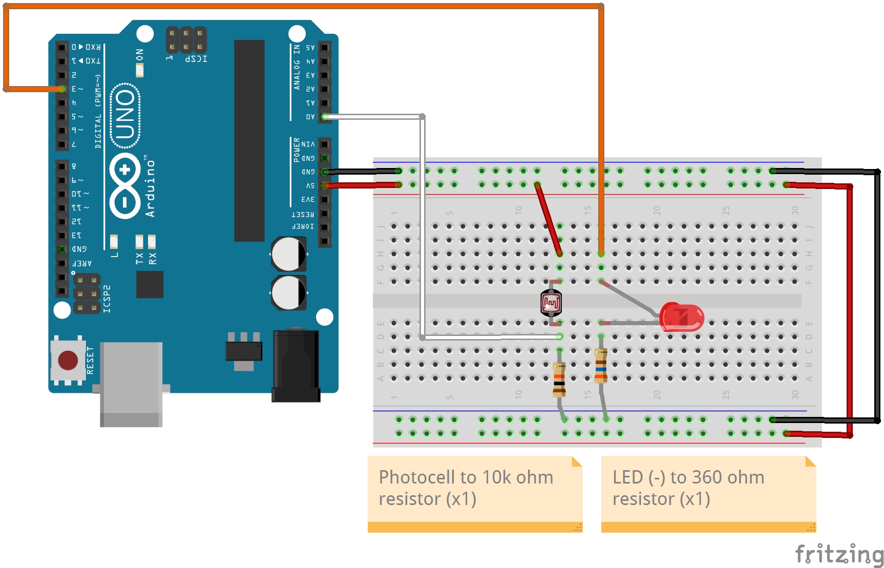
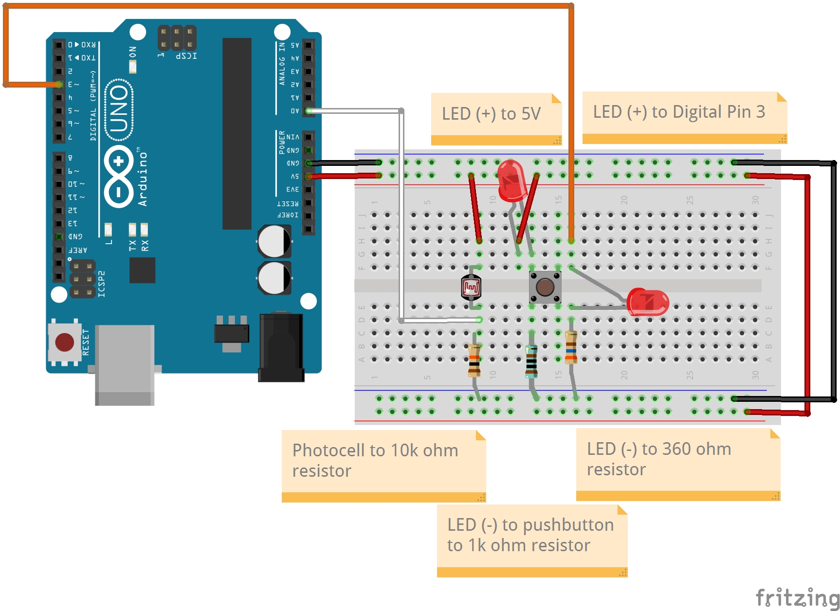
Added another resistor to decrease the "noise":
Fritzing Wiring Diagram - Adding Second Pushbutton
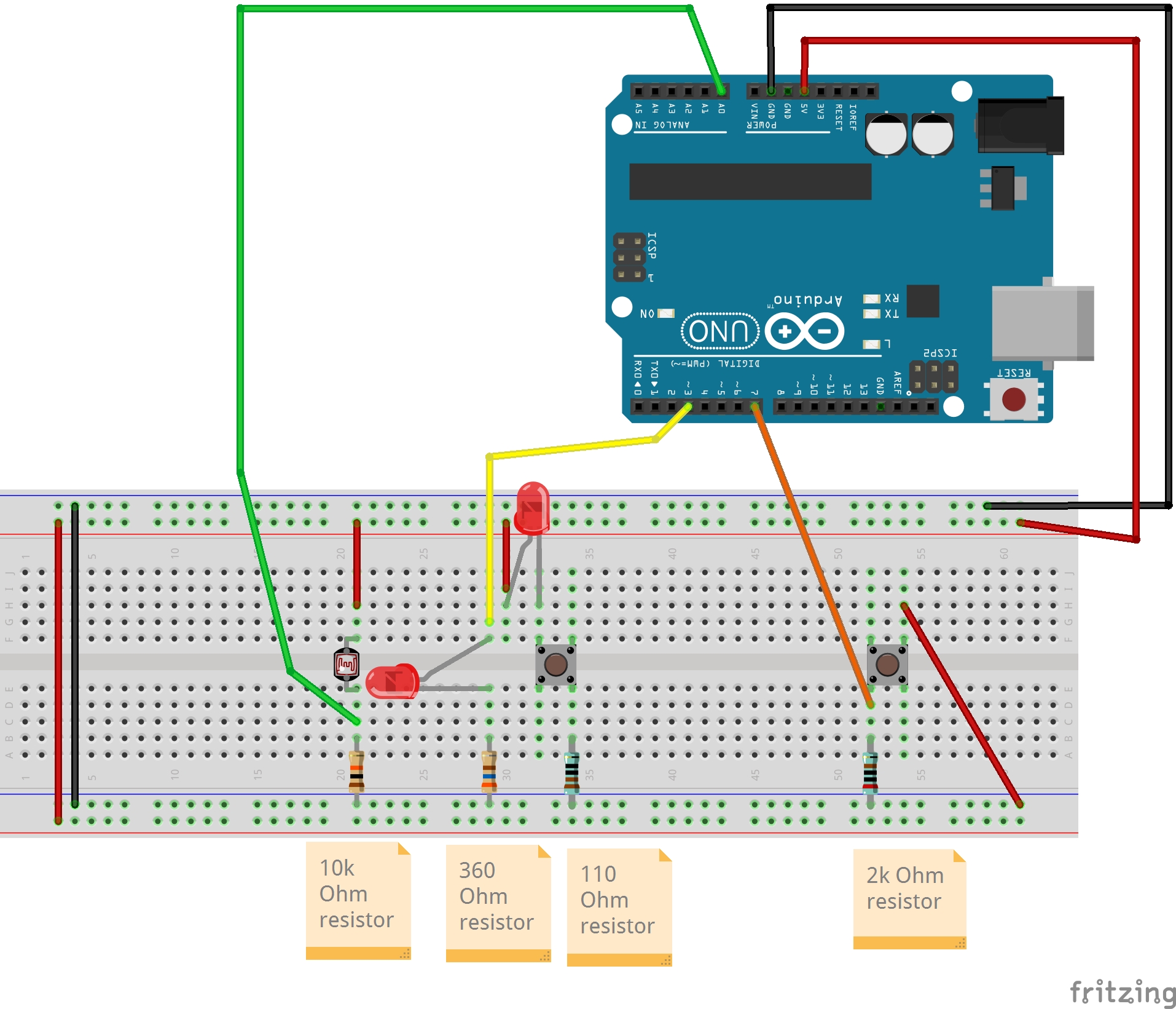
Figure 13: Fritzing Diagram of second pushbutton

Used the following python code in Google Colab to plot the graph:
import matplotlib.pyplot as plt
import numpy

x = [setpoint_data]
x2 = [ambient_lighting_data]
y = numpy.arange(len(x))
plt.plot(y, x, y, x2)
plt.table("PID Photocell Resistor Plotter - setchange() function")
plt.xlabel("Time (microseconds)", fontsize=14)
plt.ylabel("Ambient Lighting", fontsize=14)
Figure 14: Google Colab Python Code

Google Colab - Python Plot of Second Pushbutton
Figure 15: Google Colab Python Graph

GitHub - repository - MicroCon2023:
MicroCon2023-GitHub

4. Results
The Photocell resistor's ability to real-time gauge the ambient lighting of a room takes a bit of finagling with the code but it can be done. It's a great way to practice Python coding and Arduino coding then apply it to a PID control system.

5. Discussion
The biggest challenge for me was learning how to collect data from the Arduino Serial monitor then use Python coding to plot the dataset.