CE351 Lab 2023 Spring
Lab 3 - LCDs, Sensors, and Actuators
Name: Simon Gorman Email:
sbgorman@fortlewis.edu
1. LCDs, Sensors, and Actuators
2. Introduction
We were tasked with using an LCD as a display, use
temperature, humidity, ultrasonic, remote sensors, and motors as
actuators.
3. Materials and Methods
Materials
Quantity
Arduino Elegoo Uno R3
1
Breadboard
1
Jumper wires
16-20
LCD1602 display
1
Pushbutton
1
10k resistor
1
220 resistor
2
16 MHz Oscillator
1
LEDs (any color)
2
Thermistor (thermal resistor)
1
DHT11 sensor
1
TMP36 sensor
1
IR receiver module
1
Potentiometer
1
IR remote
1
4-digit seven-segment display (SSD)
1
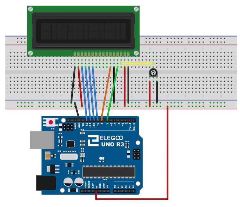
Wired up the Arduino Uno Elegoo R3 to the LCD1602, like this:
Figure 01: Wiring diagram of the Arduino Uno Elegoo R3,
potentiometer, and LCD1602
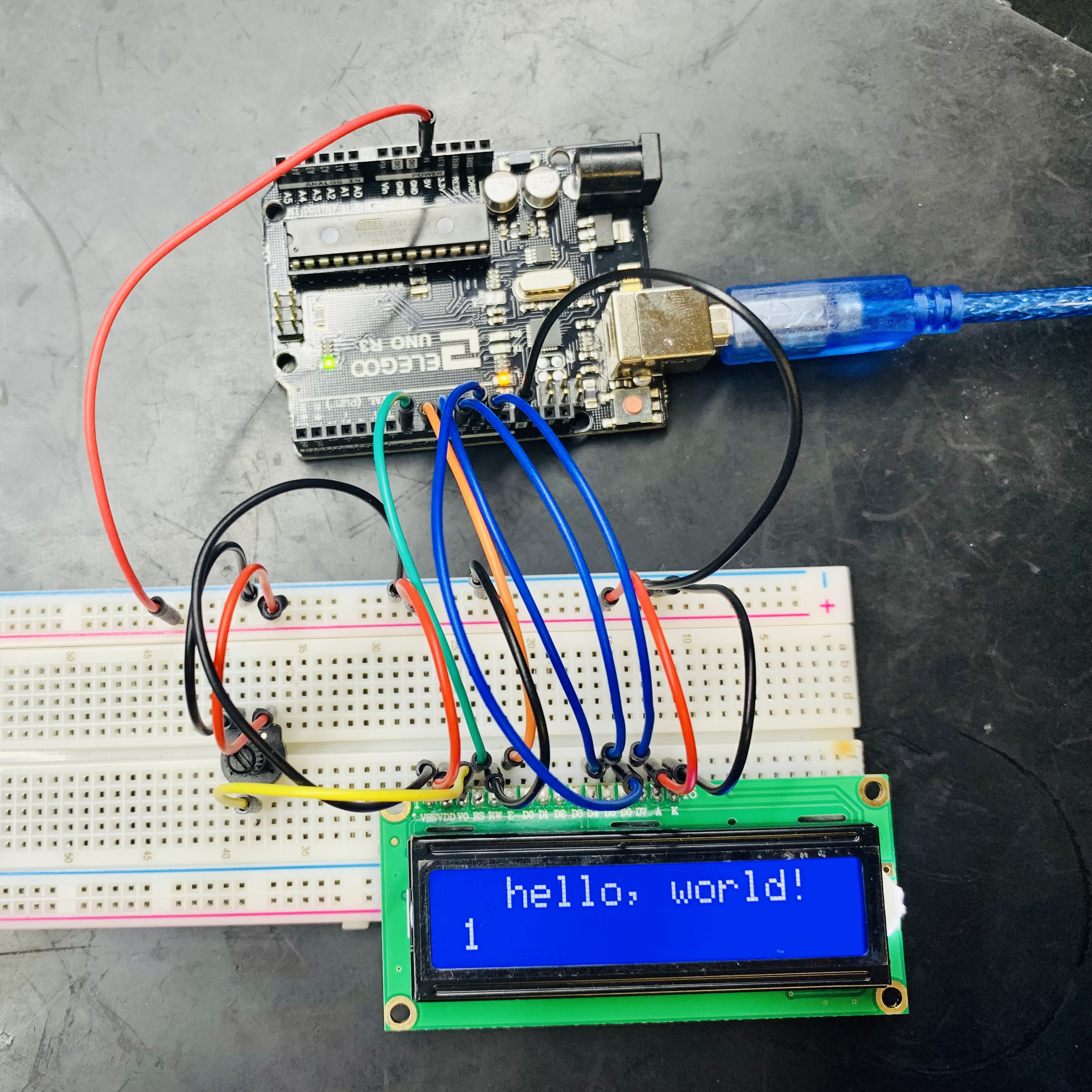
Initial testing of the LCD1602 by printing 'hello world!' using the
Arduino code (see Fig. 02) onto the LCD display (see Fig. 03):
// include the library code:
#include <LiquidCrystal.h>

// initialize the library with the numbers of the interface pins
LiquidCrystal lcd(7, 8, 9, 10, 11, 12);

// Task 1 - Display "Hello, World!" starting from the second
// rectangle on the same line
void setup() {
  // set up the LCD's number of columns and rows:
  lcd.begin(16, 2);
  // Print a message to the LCD.
  lcd.print(" Hello, World!");  // added a space before the "H"
}

void loop() {
  // set the cursor to column 0, line 1
  // (note: line 1 is the second row, since counting begins with 0):
  lcd.setCursor(0, 1);
  // print the number of seconds since reset:
  lcd.print(millis() / 1000);
}
Figure 02: Original Arduino coding for initial testing of the
LCD1602 display
10k
Figure 03: LCD1602 displaying 'hello world!' with original code
Task
1LCD - Display 'Hello
World" on the second rectangle
Display the 'Hello
World!' starting from the second rectangle on the same line
Arduino code for shifting the 'hello world!' two positions to the right
(see Fig. 04):
// include the library code:
#include <LiquidCrystal.h>

// initialize the library with the numbers of the interface pins
LiquidCrystal lcd(7, 8, 9, 10, 11, 12);

// Task 1 - Display "Hello, World!" starting from the second rectangle
// on the same line
void setup() {
  // set up the LCD's number of columns and rows:
  lcd.begin(16, 2);
  // Print a message to the LCD.
  lcd.print(" Hello, World!"); // added a space before the "H"
}

void loop() {
 // set the cursor to column 0, line 1
 // (note: line 1 is the second row, since counting begins with 0):
 lcd.setCursor(0, 1);
 // print the number of seconds since reset:
 lcd.print(millis() / 1000);
}
Figure 04:
Arduino
code to shift the phrase 'hello world!' two positions to the right.
The 'hello world!' displayed on the LCD (see Fig. 05):
Figure 05: Displaying 'hello world!' on the LCD1602
Task
2 LCD - Count to 5
then reset to 0
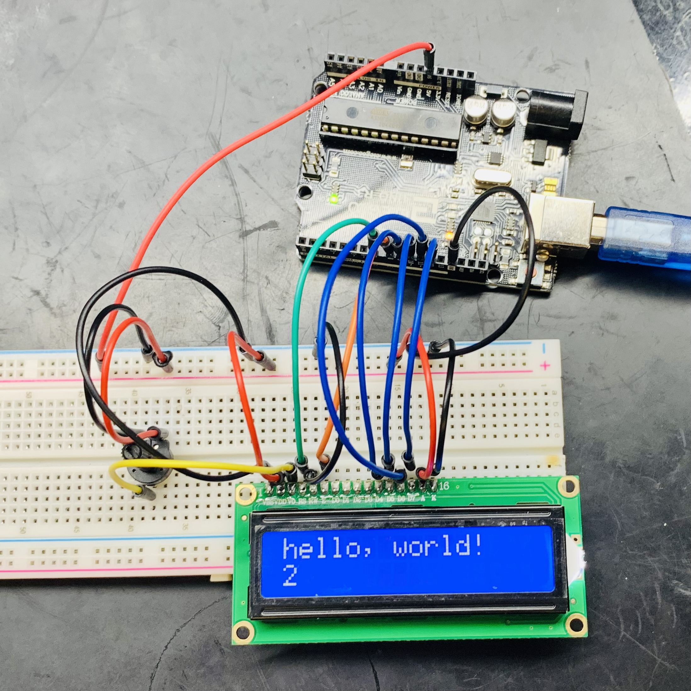
Count to 5 and then reset to 0, then start over
Used the following Arduino code to reset the counter to zero for every
5th second:
// include the library code:
#include <LiquidCrystal.h>

// initialize the library with the numbers of the interface pins
LiquidCrystal lcd(7, 8, 9, 10, 11, 12);

void setup() {
  // set up the LCD's number of columns and rows:
  lcd.begin(16, 2);
  // Print a message to the LCD.
  lcd.print("Hello, World!"); // added a space before the "H"
}

// Task 2 - Count to 5 and then reset to 0, then start over
 void loop() {
   for (int cnt = 0; cnt <= 5; cnt++){
   lcd.setCursor(0, 1);
   lcd.print(cnt);
   delay(1000);
   }
 }
Figure 06: Arduino code to reset counter
Video 01: Youtube video of the LCD count going to 5 then resetting to 0
Task 3LCD - Scrolling Text Given
that the command 'lcd.clear()' will clear out everything on the LCD, I
modified the following code so it could scroll 'Durango' on the bottom
row of the LCD to the right, flash 'Durango' 3 times in the center,
then scroll off screen to the right and start all over:
// include the library code:
#include <LiquidCrystal.h>

// initialize the library with the numbers of the interface pins
LiquidCrystal lcd(7, 8, 9, 10, 11, 12);

void setup() {
  // set up the LCD's number of columns and rows:
  lcd.begin(16, 2);
}

// Task 3 - scroll to the right, flash 'Durango' 3 times in the center,
// scroll to the right off screen, then start all over
void loop() {
  // scroll 4 positions to the right to center 'Durango'
 for (int positionCounter = 0; positionCounter < 4; positionCounter++)
{
    // scroll one position right:
    lcd.setCursor(0,1);
    lcd.print("Durango");
    lcd.scrollDisplayRight();
    // wait a bit:
    delay(100);
    }
  // Flashed 'Durango' 3 times
 for(int count=0; count<3; count++
{
    // Turn off the display:
    lcd.noDisplay();
    delay(400);
    // Turn on the display:
    lcd.display();
    delay(400);
    }
  // Scrolled 'Durango' 15 positions offscreen to the right
 for (int positionCounter = 0; positionCounter <= 15; positionCounter++)
{
    // scroll one position right:
    lcd.scrollDisplayRight();
    //lcd.scrollDisplayRight();
    // wait a bit:
    delay(100);
    }
}
Figure 07: Arduino
code to scroll 'Durango' on the LCD Video 02: Youtube video of my
scrolling text
Task
4Thermistor Sensor Show
room temperature on the LCD. Use your finger to
warm it up see if it changes.
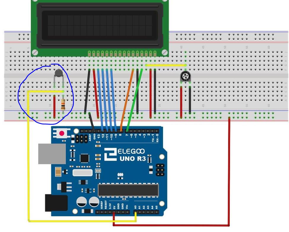
I
used the following diagram for wiring my Arduino,
thermistor, and 10k resistor:
Figure 08: Arduino wiring to the thermistor
I
used the following code to have the thermistor
temperature readings be displayed on the LCD:
// include the library code:
#include <LiquidCrystal.h>

int tempPin =0; // Task 4

// initialize the library with the numbers of the interface pins
LiquidCrystal lcd(7, 8, 9, 10, 11, 12);

void setup() {
  // set up the LCD's number of columns and rows:
  lcd.begin(16, 2);
}

// Use a Thermistor to measure the temperature
void loop(){
  int tempReading = analogRead(tempPin);
  double tempK = log(10000.0 * ((1024.0 / tempReading - 1)));
  tempK = 1 / (0.001129148 + (0.000234125 + (0.0000000876741 * tempK * tempK )) * tempK );
  float tempC = tempK - 273.15; // Convert Kelvin to Celsius
  float tempF = (tempC * 9.0)/ 5.0 + 32.0; // Convert Celsius to Fahrenheit
  lcd.setCursor(0,0);
  lcd.print("Temp         C");
  // Display Temperature in F
  // lcd.print("Temp         F");
  lcd.setCursor(6,0);
  // Display Temperature in C
  lcd.print(tempC);
  // Display Temperature in F
  // lcd.print(tempF);
  delay(500);
Figure 09: Arduino code of
reading room temperature with a thermistor to an LCD
Video 03: Youtube video of LCD printing
room
temperature
Task 5DHT sensor Modify
the code to display in the form below. Simply blow at the sensor to
change the temperature and the humidity to test it. Show a
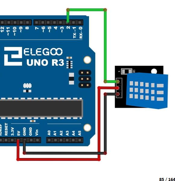
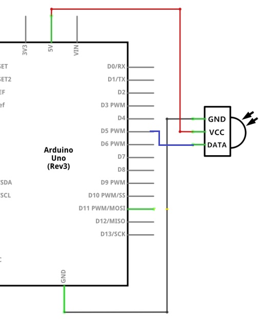
demonstration video in your report. I removed the thermistor then wired the DHT sensor to my Arduino and LCD by using the
following wiring diagrams:
Figure 10: Simplified diagram DHT sensor wiring to the Arduino
board
Figure 11: Realistic diagram of DHT sensor wiring to the Arduino
board
I used the following code to read from the
DHT sensor and display the readings on the LCD:
// To read humidity
// include the library code:
#include <LiquidCrystal.h>
#include <SimpleDHT.h>

// initialize the library with the numbers of the interface pins
LiquidCrystal lcd(7, 8, 9, 10, 11, 12);

// for DHT11,
// VCC: 5V or 3V
// GND: GND
// DATA: 2
int pinDHT11 = 2;
SimpleDHT11 dht11;

void setup() {
  // set up the LCD's number of columns and rows:
  lcd.begin(16, 2);
}

// Use a DHT sensor to measure the temperature
// and humidity
void loop(){
  lcd.setCursor(0,0);
  byte temperature = 0;
  byte humidity = 0;
  byte data[40] = {0};
  dht11.read(pinDHT11, &temperature, &humidity, data);
  lcd.print((int)temperature); lcd.print("  *C, ");
  lcd.print((int)humidity); lcd.print(" %");
  // DHT11 sampling rate is 0.5Hz.
  delay(2000);
}
Figure 12: Arduino code to read humidity
I
modified the code from Fig. 11 to display the room temperature and
humidity on the LCD:
// include the library code: #include <LiquidCrystal.h> #include <SimpleDHT.h>
// initialize the library with the numbers of the interface pins LiquidCrystal lcd(7, 8, 9, 10, 11, 12);
// for DHT11, // VCC: 5V or 3V // GND: GND // DATA: 2 int pinDHT11 = 2; SimpleDHT11 dht11;
void setup() { // set up the LCD's number of columns and rows: lcd.begin(16, 2); lcd.print("Temp C"); }
// Use a DHT sensor to measure the temperature // and humidity void loop(){ byte temperature = 0; byte humidity = 0; byte data[40] = {0}; dht11.read(pinDHT11, &temperature, &humidity, data);
Figure 13: Arduino code for reading humidity and temperature
from the
DHT sensor
Video 04: Youtube video of displaying temp and humidity on the LCD
Task
6 cancelled - don't have to do this
task Task 7IR
Remote and Sensor Used
the following diagram to wire the IR sensor to the Arduino Uno
(see Fig. 14) Figure 14: Simplified wiring diagram
of the
IR module connected to the Arduino Uno R3
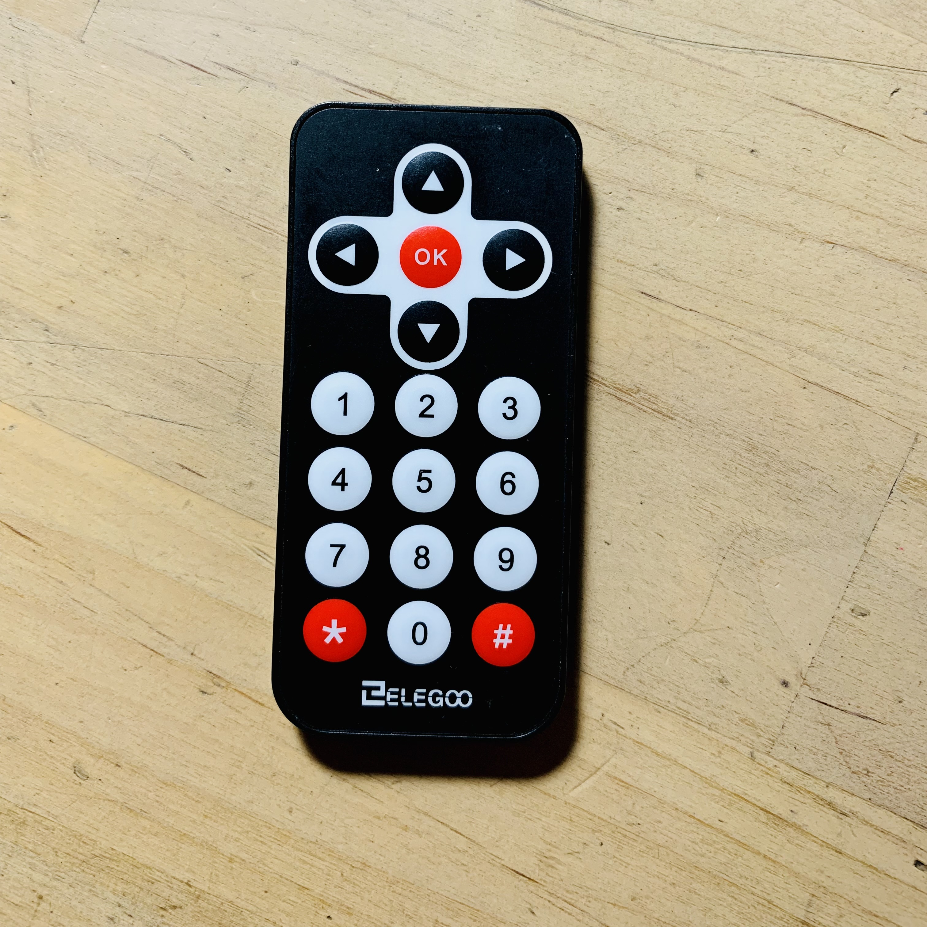
Modified
the following code (see Fig. 15) to match the new IR remote (see Fig.
17)
controller's commands (see Fig. 16):
#include <IRremote.h>
#include <LiquidCrystal.h>
//                BS  E  D4 D5  D6 D7
LiquidCrystal lcd(7, 8, 9, 10, 11, 12);
int receiver = 5; // Signal Pin of IR receiver to Arduino Digital Pin 5
IRrecv irrecv(receiver);     // create instance of 'irrecv'
decode_results results;      // create instance of 'decode_results'
void translateIR() // takes action based on IR code received
{
  switch(results.value)
  {
  case 0xFFA25D: lcd.print("POWER         "); break;
  case 0xFFE21D: lcd.print("FUNC/STOP     "); break;
  case 0xFF629D: lcd.print("VOL+          "); break;
  case 0xFF22DD: lcd.print("FAST BACK     ");  break;
  case 0xFF02FD: lcd.print("PAUSE         ");  break;
  case 0xFFC23D: lcd.print("FAST FORWARD  ");  break;
  case 0xFFE01F: lcd.print("DOWN          ");  break;
  case 0xFFA857: lcd.print("VOL-          ");  break;
  case 0xFF906F: lcd.print("UP            ");   break;
  case 0xFF9867: lcd.print("EQ            ");  break;
  case 0xFFB04F: lcd.print("ST/REPT       ");   break;
  case 0xFF6897: lcd.print("0             ");    break;
  case 0xFF30CF: lcd.print("1             ");    break;
  case 0xFF18E7: lcd.print("2             ");    break;
  case 0xFF7A85: lcd.print("3             ");    break;
  case 0xFF10EF: lcd.print("4             ");    break;
  case 0xFF38C7: lcd.print("5             ");    break;
  case 0xFF5AA5: lcd.print("6             ");    break;
  case 0xFF42BD: lcd.print("7             ");    break;
  case 0xFF4AB5: lcd.print("8             ");    break;
  case 0xFF52AD: lcd.print("9             ");    break;
  case 0xFFFFFFFF: lcd.print("REPEAT      ");break;
  default:
  lcd.print("INVALID          ");
  }
  delay(500); // Do not get immediate repeat
} //END translateIR
void setup()
{
  lcd.begin(16,2);
  irrecv.enableIRIn(); // Start the receiver
}
void loop()
{
  if (irrecv.decode(&results)) // have we received an IR signal?
  {
    lcd.setCursor(0,0);
    lcd.print(results.value);
    lcd.setCursor(0,1);
    translateIR();
    irrecv.resume(); // receive the next value
  }
}
Figure 15: Original Arduino code for the IR contoller
//Task 7 - IR receiver
#include <IRremote.h>
#include <LiquidCrystal.h>
//                BS  E  D4 D5  D6 D7
LiquidCrystal lcd(7, 8, 9, 10, 11, 12);
int receiver = 5; // Signal Pin of IR receiver to Arduino Digital Pin 5
IRrecv irrecv(receiver);     // create instance of 'irrecv'
decode_results results;      // create instance of 'decode_results'
void translateIR() // takes action based on IR code received
{
  switch(results.value)
  {
  case 0xFF42BD: lcd.print("*             "); break;
  case 0xFF52AD: lcd.print("#             "); break;
  case 0xFF629D: lcd.print("UP            "); break;
  case 0xFF22DD: lcd.print("LEFT          ");  break;
  case 0xFF02FD: lcd.print("OK            ");  break;
  case 0xFFC23D: lcd.print("RIGHT         ");  break;
  case 0xFFA857: lcd.print("DOWN          ");  break;
  case 0xFF4AB5: lcd.print("0             ");   break;
  case 0xFF6897: lcd.print("1             ");    break;
  case 0xFF9867: lcd.print("2             ");    break;
  case 0xFFB04F: lcd.print("3             ");    break;
  case 0xFF30CF: lcd.print("4             ");    break;
  case 0xFF18E7: lcd.print("5             ");    break;
  case 0xFF7A85: lcd.print("6             ");    break;
  case 0xFF10EF: lcd.print("7             ");    break;
  case 0xFF38C7: lcd.print("8             ");    break;
  case 0xFF5AA5: lcd.print("9             ");    break;
  case 0xFFFFFFFF: lcd.print("REPEAT      ");break;
  default:
  lcd.print("INVALID          ");
  }
  delay(500); // Do not get immediate repeat
} //END translateIR
void setup()
{
  lcd.begin(16,2);
  irrecv.enableIRIn(); // Start the receiver
}
void loop()
{
  if (irrecv.decode(&results)) // have we received an IR signal?
  {
    lcd.setCursor(0,0);
    lcd.print(results.value);
    lcd.setCursor(0,1);
    translateIR();
    irrecv.resume(); // receive the next value
  }
}
Figure
16: Modified code to match the new IR remote Figure 17: Coded to match this
Elegoo IR remote
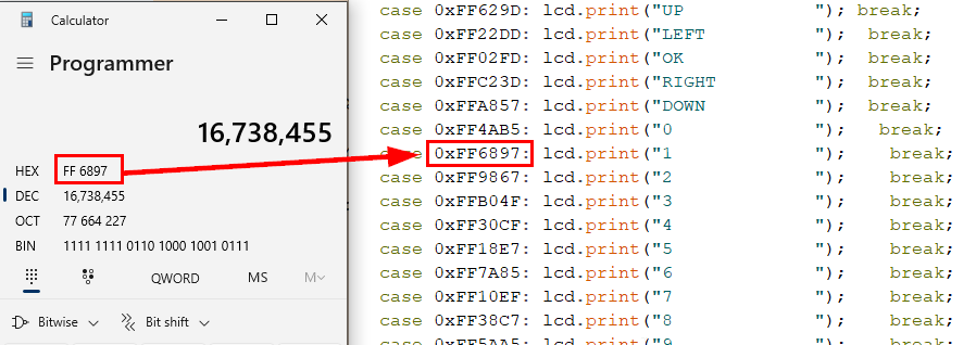
Re-mapped the IR remote controller Arduino
code by
converting each decimal value into hex so the IR remote commands
matched the Arduino code (see Fig. 18).
Figure 18: Used the Windows Calculator's Programmer feature to
convert
from DEC to HEX
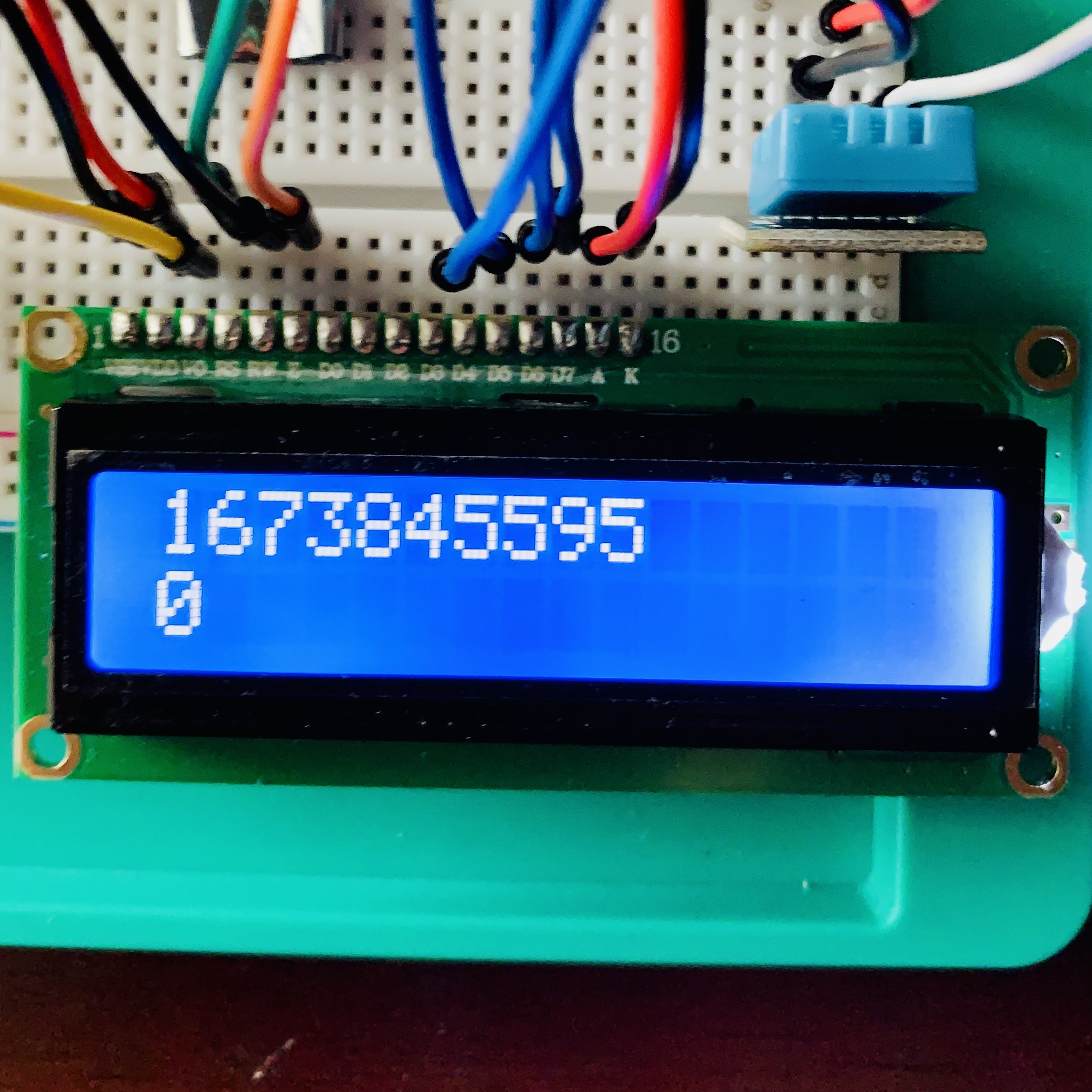
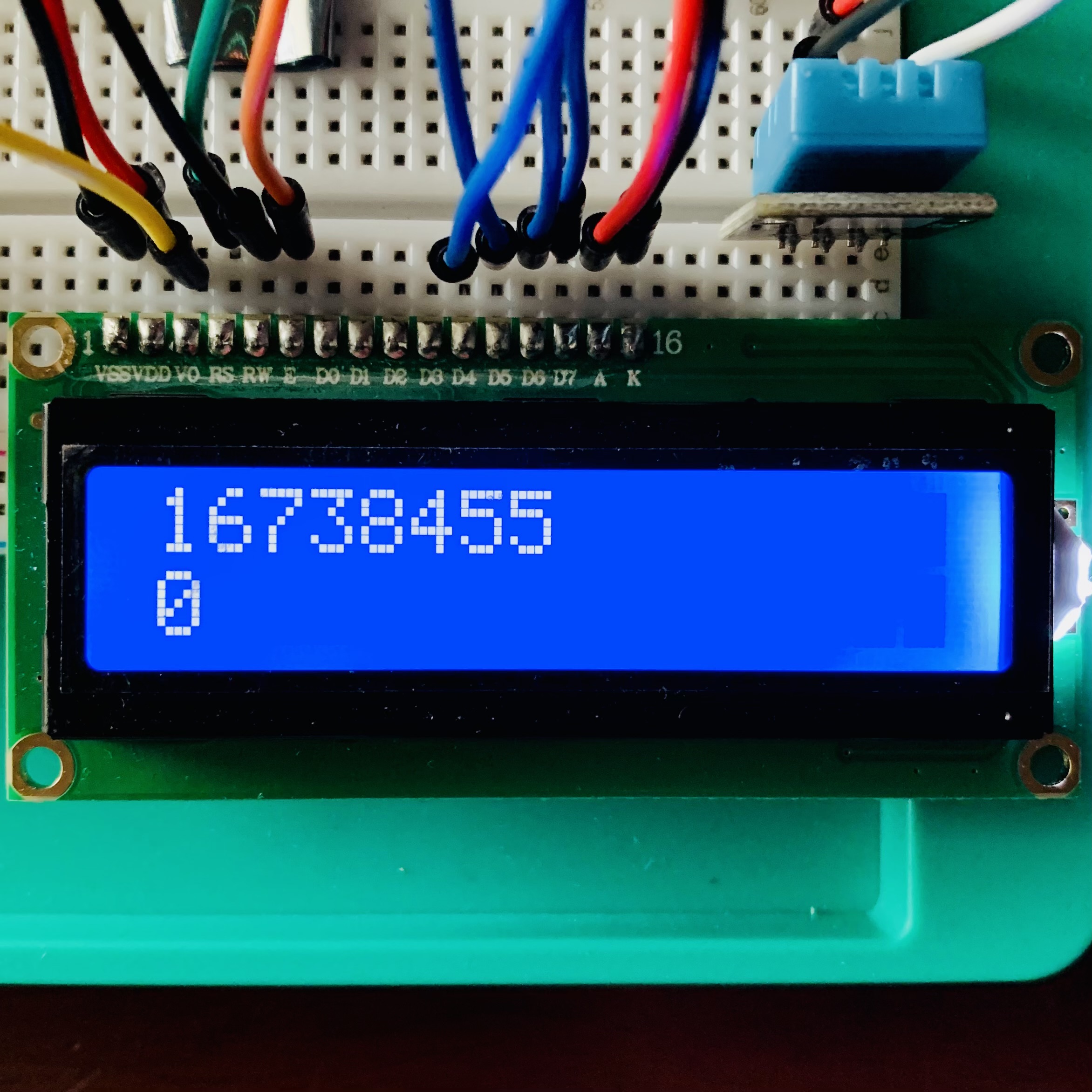
If the number printed to the LCD suddenly
becomes longer after printing 'REPEAT', in my case it added "95" to the
end of the decimal number (see Fig. 19), reboot the Arduino Uno so it
can print the correct decimal number (see Fig. 20).
Figure 19: Extra numbers added to the decimal value
Figure 20: After powering the Arduino Uno on/off and it prints
the
correct decimal value
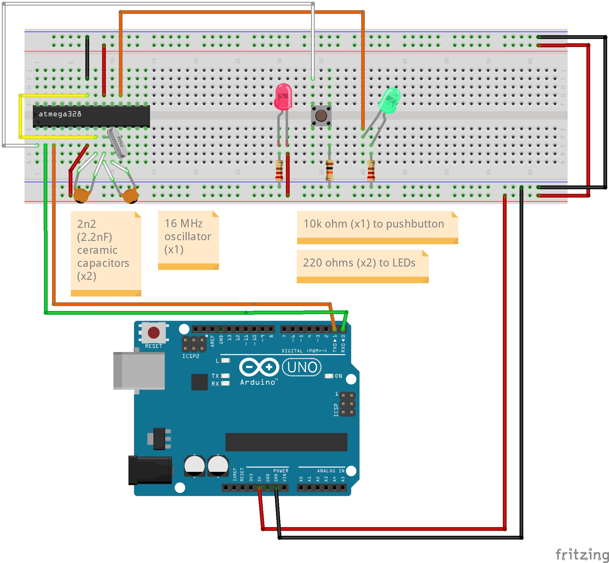
Task 8The
Barebone ATmega328p I (very carefully) removed the ATmega328p from the Arduino Uno then wired the ATmega328p to the breadboard and
Arduino Uno like this (see Fig. 00):
Figure 21: ATmega328p wiring diagram with the pushbutton as the Reset
Used the following code to test the
Barebone ATmega32p:
// the setup function runs once when you press reset or power the board
void setup() {
  // initialize digital pin LED_BUILTIN as an output.
  pinMode(12, OUTPUT);
}

// the loop function runs over and over again forever
void loop() {
  digitalWrite(12, HIGH);   // turn the LED on (HIGH is the voltage level)
  delay(250);                       // wait for a second
  digitalWrite(12, LOW);    // turn the LED off by making the voltage LOW
  delay(250);                       // wait for a second
}
Figure 22: Blink Example with LED_BUILTIN as pin 12 on the ATmega32p
I did one test where the Reset of the ATmega328p was directly connected
the Reset pin on the Arduino board (see Video 05) and another test
where the ATmega328p's Reset pin was wired to a pushbutton (see Video 06):
Video 05: ATmega328p wired directly to the Arduino Uno's Reset pin
Video 06: ATmega328p wired to a pushbutton with a 10k pull-up resistor
Task 9The Interrupts Used
the barebone ATMega328p to build a portable digital temperature meter.
Used an Interrupt Service Routine to update the temperature display. The
temperature/humidity sensor is the DHT11, the display unit is the
4-digit 7-segment display. 4. Results []