| Materials | Quantity |
| Arduino Uno R3 board (or similar
model) |
1 |
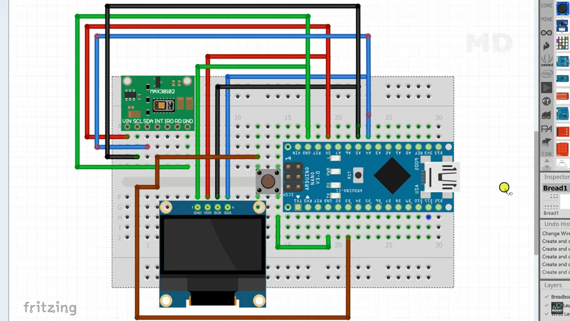
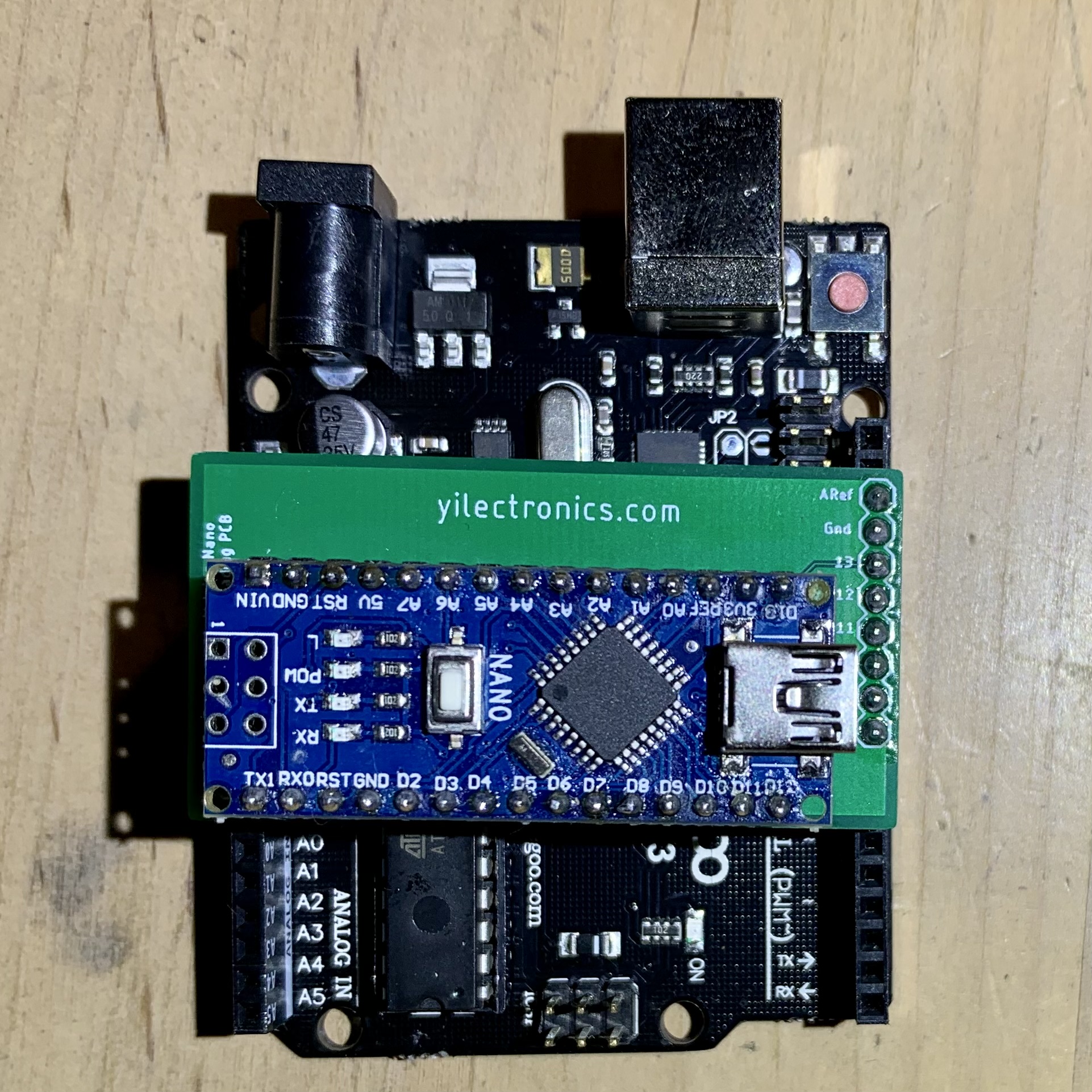
| Arduino Nano bootloader board |
1 |
| MAX30102 Heart Rate Sensor and
Oximeter Module |
1 |
| SSD1306 OLED Display (0.96 inch) |
1 |
| Arduino Nano board |
1 |
| Breadboard (half or full-size) |
1 |
| Pushbutton | 1 |
| Breadboard/Jumper wires |
5-6 |
|
|
|