CE351 Microcontrollers Lab 2023 Spring
Lab 1 - DC 5V, 3.3V Regulators - Power Supply Circuit for MCU
Name: Simon Gorman

Email: sbgorman@fortlewis.edu

1. Power Supply Circuit for MCU

2. Introduction

Sharpen Eagle PCB skills by using the application to draw a schematic and PCB layout of a Power Supply Circuit for MCU that fits onto a breadboard.

3. Materials and Methods


!You will need EAGLE PCB installed on your computer!

Materials Quantity
Breadboard
1
Yellow LED
1
Connector 1x02
4
Power Jack
1
3 Pin 2 Position Vertical Slide Switch
9
4.7uF capacitor
2
22uF capacitor 1
33uF capacitor 1
100uF capacitor 1
SS34_214AB Schottky diode 2
33uH 3.8A SMD inductor 1
47uH 3.8A SMD inductor 1
LM2596SX 3.3V 3.8A 1
LM2596SX 5V 3.8A 1


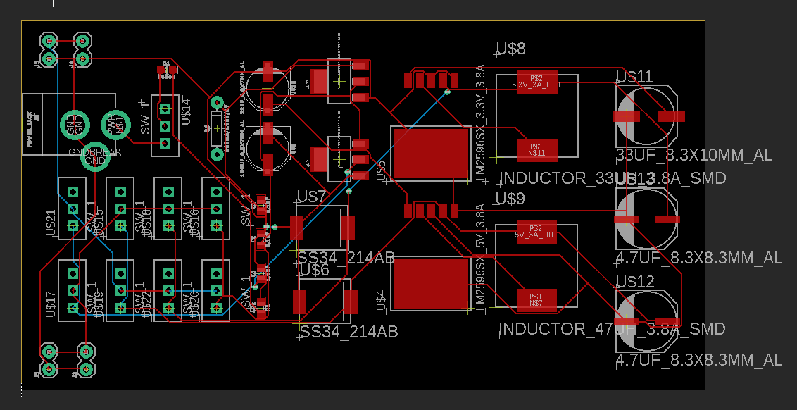
First, I built the following custom devices in EAGLE PCB:

4.7uF capacitor in PCB Eagle
Figure 01: 4.7uF capacitor in
EAGLE PCB

22uF capacitor in PCB Eagle
Figure 02: 22uF capacitor in
EAGLE PCB

33uF capacitor in PCB Eagle
Figure 03: 33uF capacitor in
EAGLE PCB

100uF capacitor in PCB Eagle
Figure 04: 100uF capacitor in EAGLE PCB

SS34_214AB - Schottky diode
Figure 05: SS34_214AB Schottky diode in EAGLE PCB

33UH 3.8A SMD inductor
Figure 06: 33uH 3.8A SMD inductor in EAGLE PCB


47UH 3.8A SMD inductor
Figure 07: 47uH 3.8A SMD inductor in EAGLE PCB

LM2596SX 3.3V 3.8A
Figure 08: LM2596SX 3.3V 3.8A in EAGLE PCB1

LM2596SX 5V 3.8A
Figure 09: LM2596SX 5V 3.8A in EAGLE PCB

Then I built the following schematic in EAGLE PCB:

PCB module schematic
Figure 10: PCB Module final EAGLE PCB schematic


After finalizing the schematic, I designed my PCB board so it would fit onto a breadboard:

PCB module airwires
Figure 11: PCB eagle board drawing layout, only airwires


PCB module autoroute
Figure 12: PCB after Autorouting the wires


PCB top copper
Figure 13: PCB eagle board red/top copper


PCB bottom copper
Figure 14: PCB eagle board blue/bottom copper

soldered PCB top side
Figure 15: Soldered components onto the PCB (top view)

soldered PCB underside
Figure 16: Soldered components onto the PCB (bottom view)


4. Results

Currently waiting for the board to be printed so I do not have my results yet.

5. Discussion
Designing a schematic and PCB was difficult but I'm sure I won't forget how to use EAGLE PCB after this project (it really tested me). I also had to redraw my board because I lost the original file (now I triple-save everything, lesson learned).