1. ESP 32 MCU with WiFi
2. The purpose of this lab is to build and verify
the functionality of the ESP module by first setting up the module,
running a blink example, connecting to accelorometer, and displaying
the output. Similarly two ESP32 modules were used to create a link
between a master and slave one that transmits data to computer and
micro SD but also one to control the acceloromter.
3. Materials and Methods
Arduino Nano/Uno
ESP32
Accelorometer
Power module
4. Results
Figure 1. Tasks 1-3 and task 7 shown for video verification.
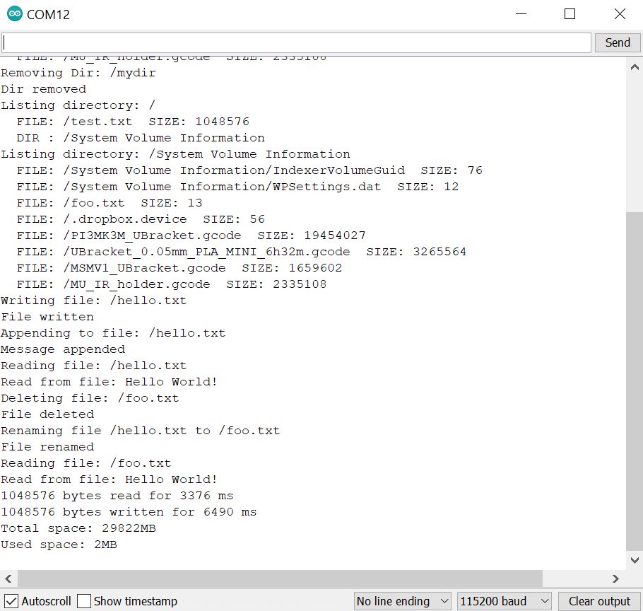
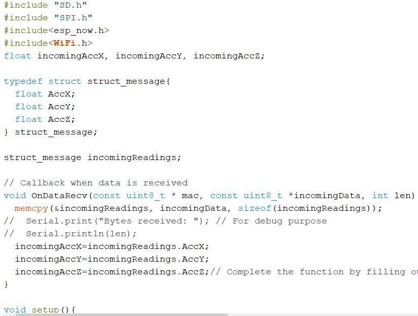
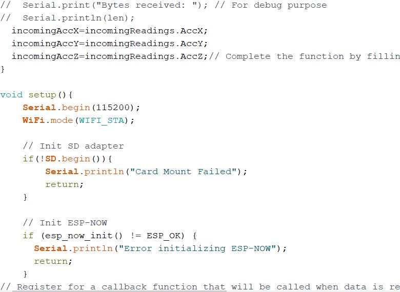
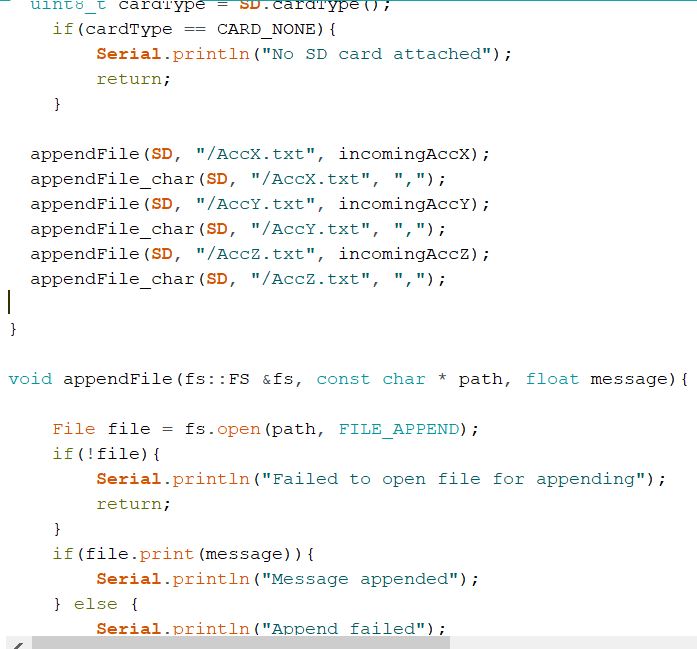
Figure 2. Verification of the ESP communication with the SD card task 4.
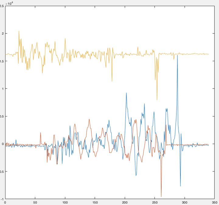
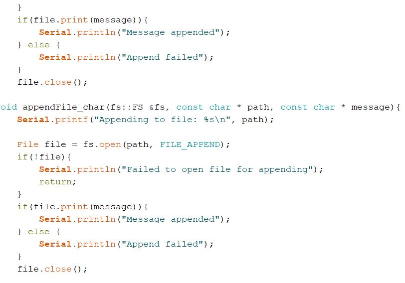
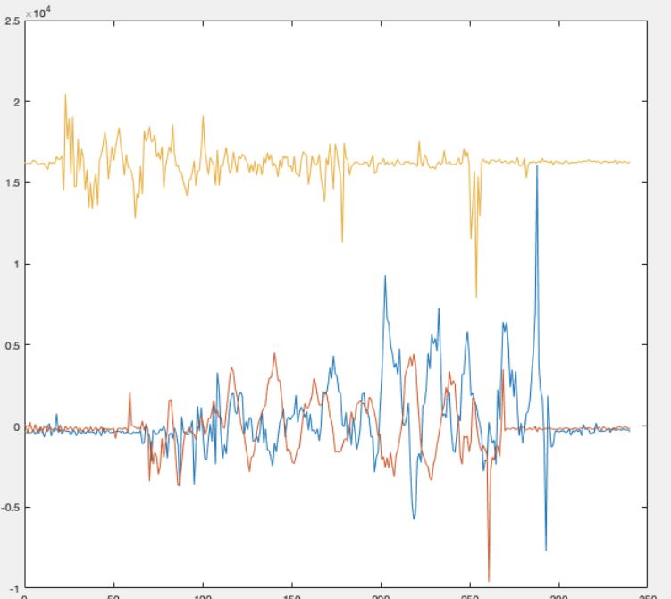
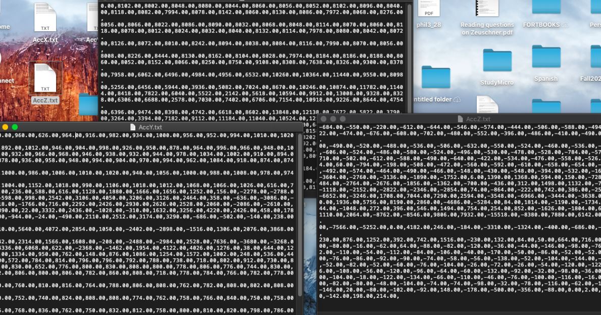
Figure 3. Data of AccX, AccY, AccZ recieved in seperate files and plotted in matlab via txt file.
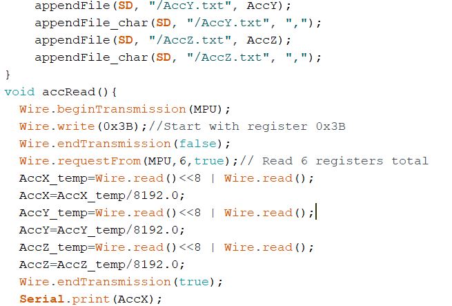
Figure 4. Data stored in seperate files using modifications to
code along with change to float and int16_t and AccX_temp modifications
for task 6.
Figure 5. Task 8 data stored to SD card connected to slave board.
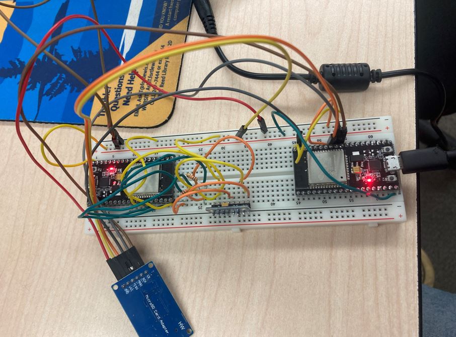
Figure 6. displays connection to the slave board.
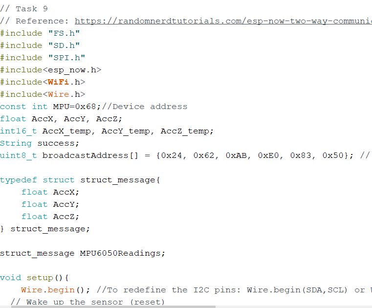
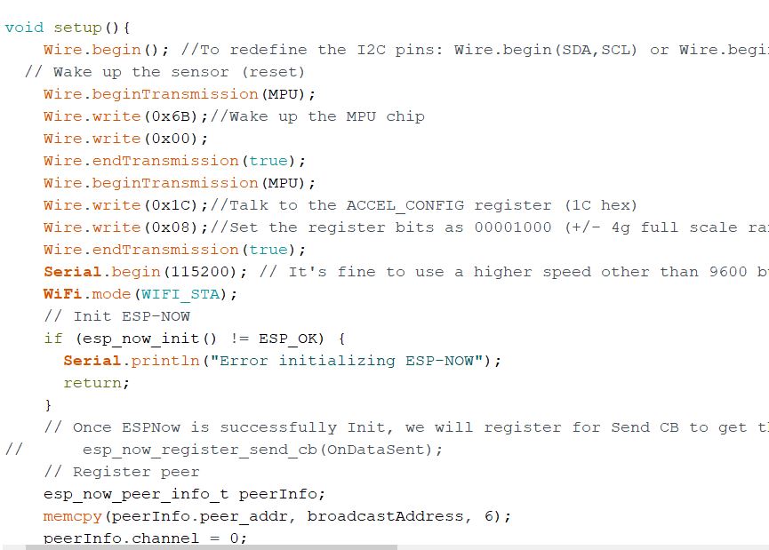
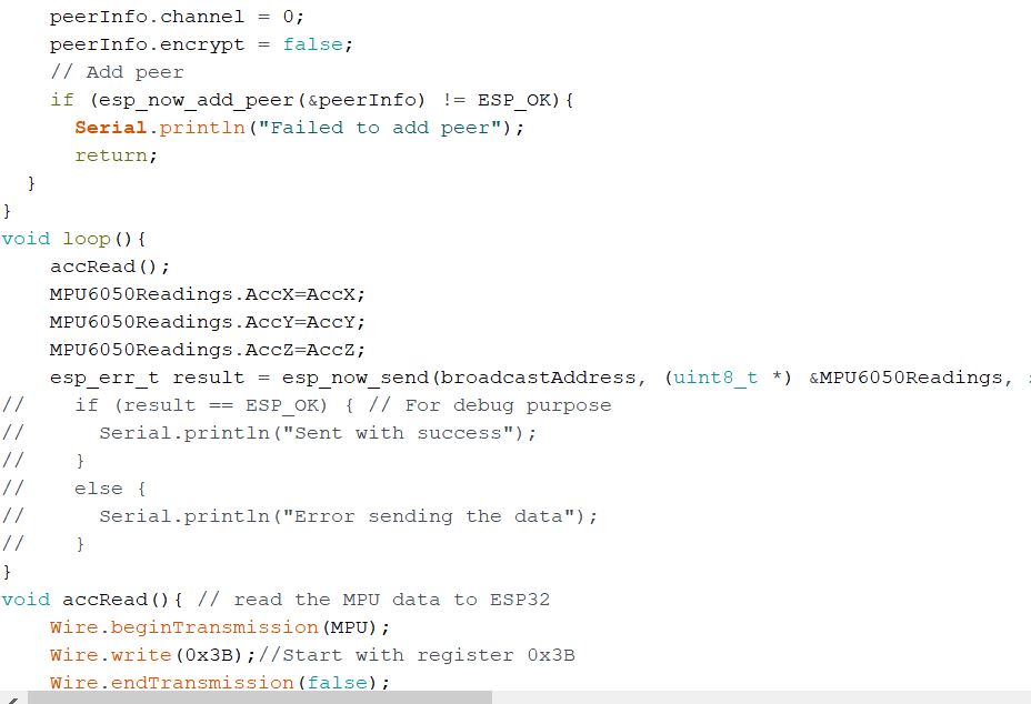
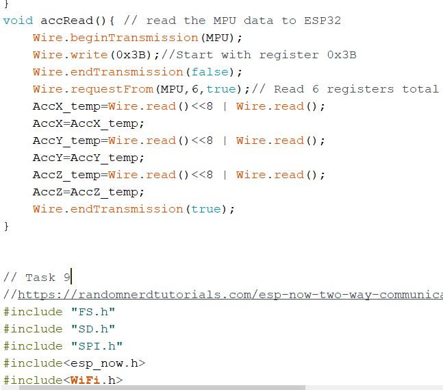
Figure 7. Clean code used for the removal of division operation in task 9.
Figure 8. Matlab used to plot final task using the master and the slave without the divison and unessisary debugging.
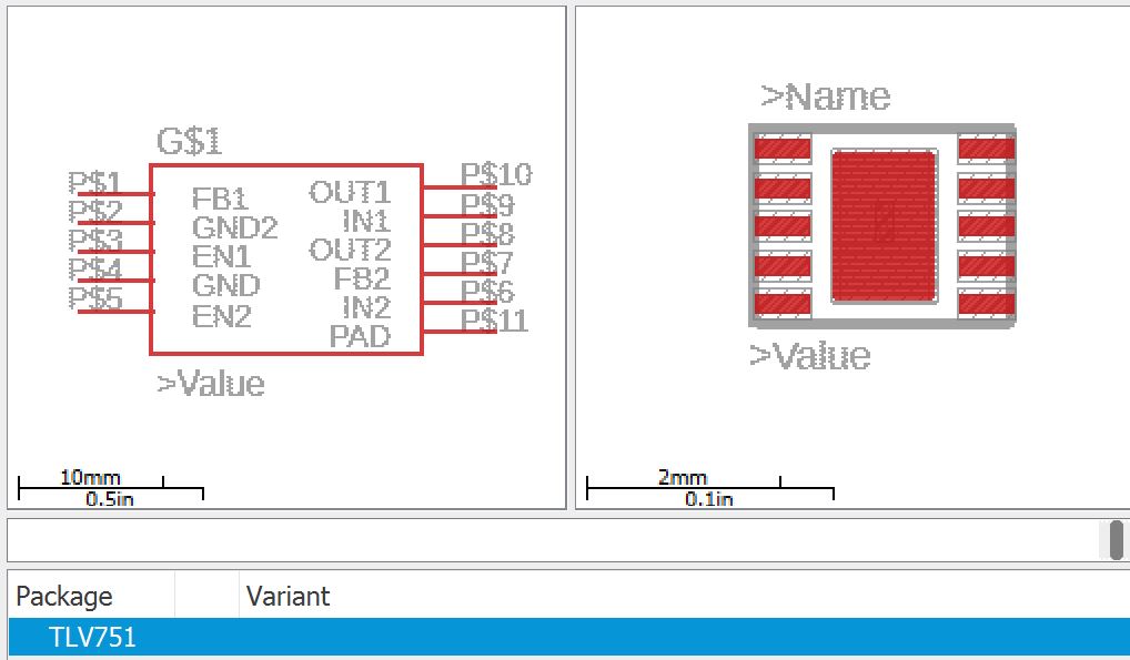
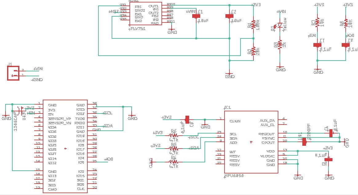
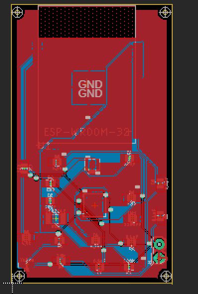
Figure 9. Data used for matlab input for task 9. Figure 10. Power module completion for the esp module. Figure 11. Schematic of ESP module. Figure 12. Final board for the ESP module.
5.
Discussion
The lab was involved but very cool to see the data transmission in
this way. The master and slave combonation to send data is a relavent
and applicable engineering device and task. The overall process and
code was good to use and learn as it added to previous knowledge of
code and its applications.