1. Design a Simple 8-Bit ALU 2. The purpose of this
lab is to build and simulate the logic of the Arithmatic Logic Unit and
to complete a layout of the ALU from previous components. The ALU is
designed to do mathmatical functions as part of a larger intergrated
curcuit.
3. Materials and Methods
LTSpice computer Application
Paper and Pencil
Electric VLSI Application
4. Results
Figure 1. 8-bit inverter component used for ALU design, fashioned from 20/10 inverter.
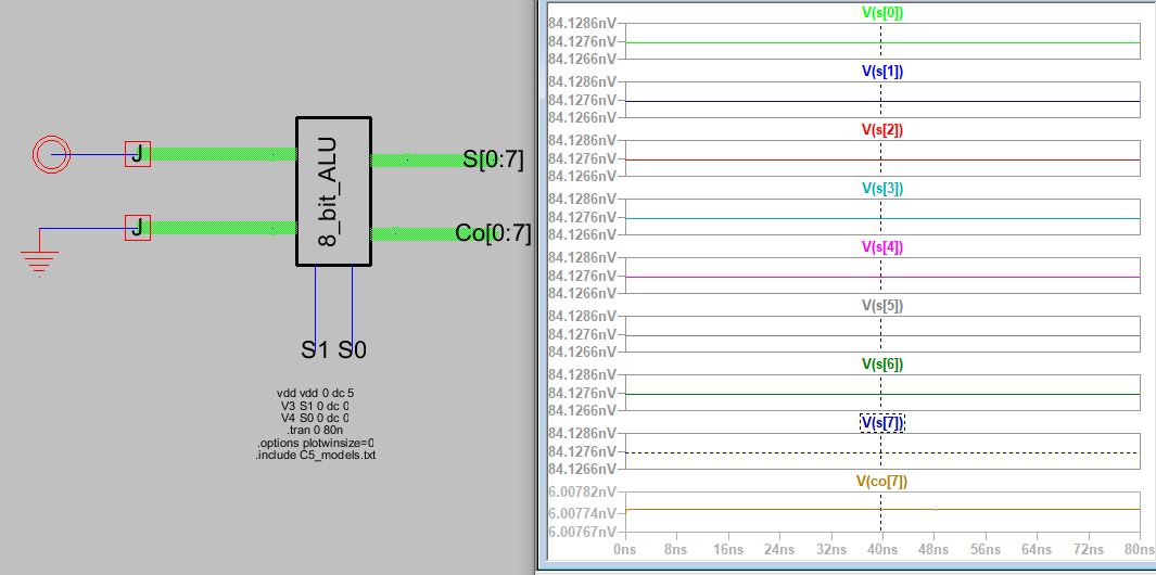
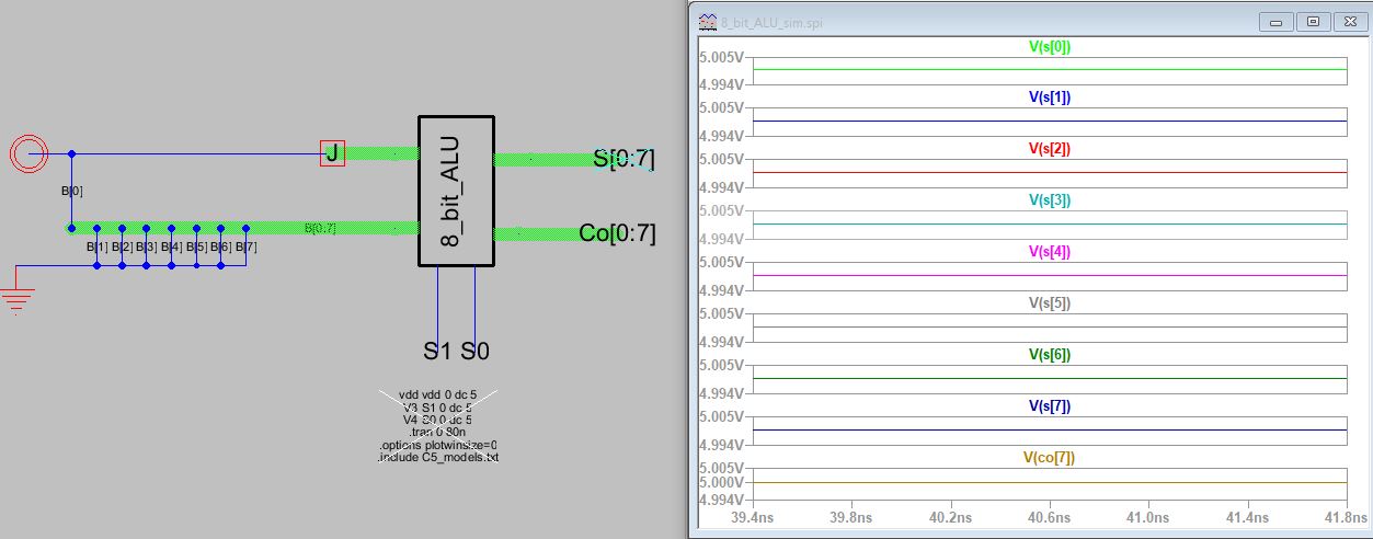
Figure 2. Simulation using LT spice of 8-bit ALU to verify AND logic.
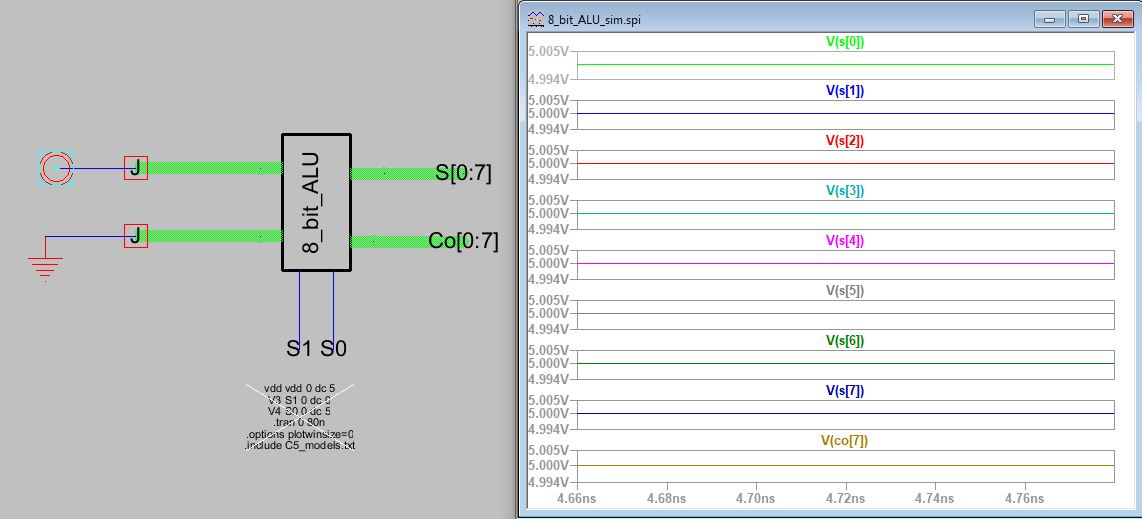
Figure 3. Simulation using LT spice of 8-bit ALU to verify OR logic.
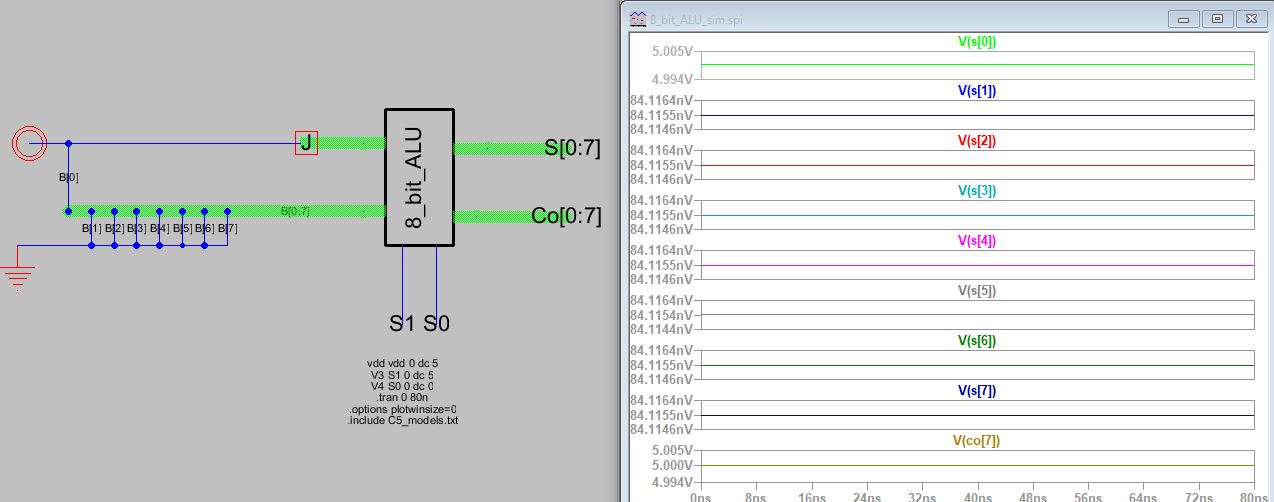
Figure 4. Simulation using LT spice of 8-bit ALU to verify ADD operation.
Figure 5. Simulation using LT spice of 8-bit ALU to verify SUB operation
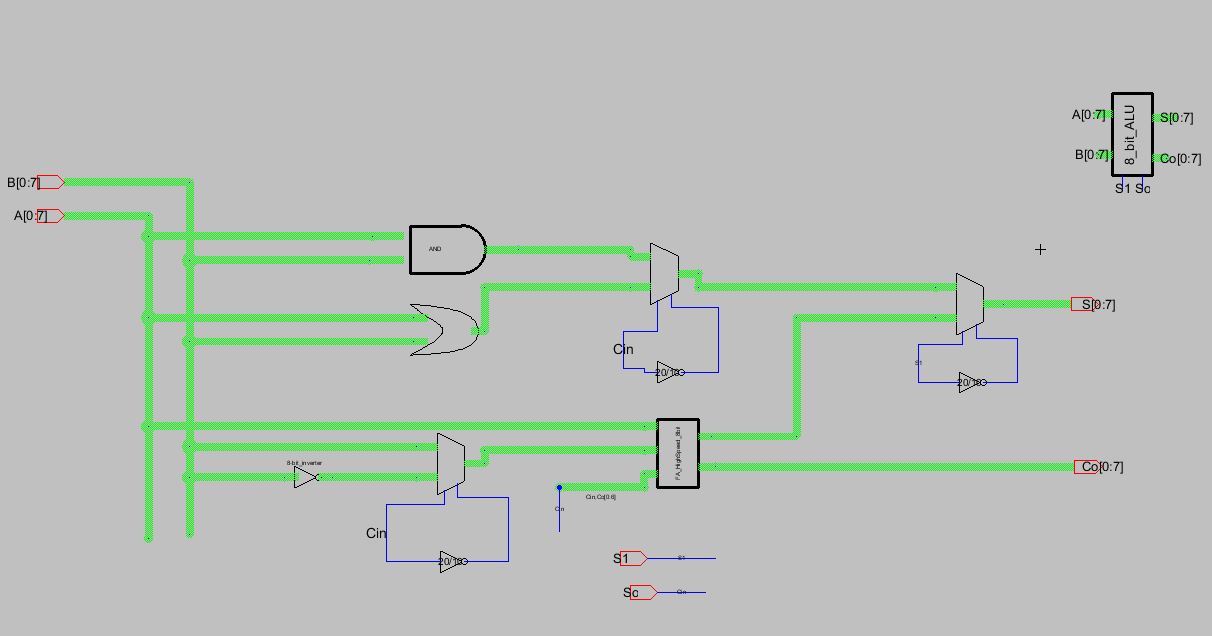
Figure 6. Schematic of the ALU shown in Electric VLSI.
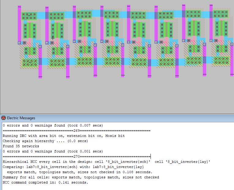
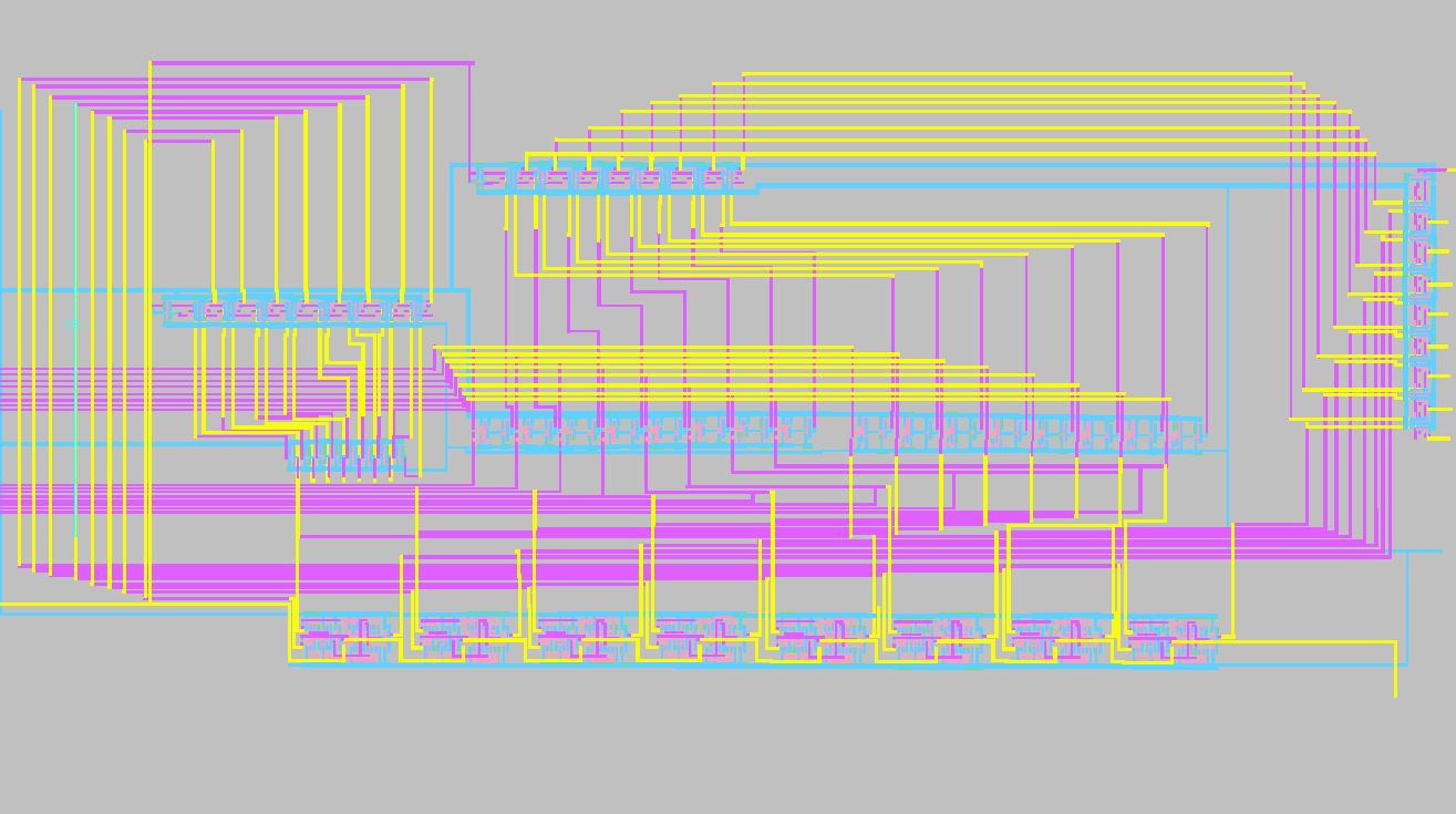
Figure 7. Final Layout of ALU shown in Electric VLSI.
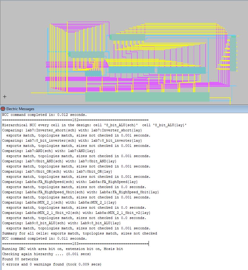
Figure 8. Final Layout of ALU shown in Electric VLSI with clean NCC topologies.
5. Discussion
The ALU was the culmanation of all the previous parts created
including the XOR, AND, and MUX. These all were challenging to create
the most challenging was the full adder and the wiring of the ALU. Many
wires and many connections used while forming the 8 bit Arthmatic Logic
Unit. Electric is a great tool for design these complex curcuits, just
make sure to save in proper location with proper name.