3D Printing Tutorial
Overview:
The purpose of the tutorial is to
utilize 3D printing technology to manufacture components for Robotics
labs or for other general purposes. To 3D print an object it must first
be designed using AutoCAD Solidworks. Once the component has been
created in Solidworks it can be exported as a STL file and opened with
Ultimaker Cura. Within Cura 3D printing settings can be modified as
well as the orientation of the part. The 3D component is then "sliced"
using Cura which will export your part as G-code which is the software
that the 3D printer uses to navigate. Once the STL has been converted
to G-code it can be loaded onto the 3D printer and constructed.
Materials:
| Materials |
Solidworks
|
Cura Ultimaker
|
Calipers
|
Glue
|
Cleaning Solution
|
Paper Towels
|
3D Printer
|
Methods:
Start AutoCAD Solidworks
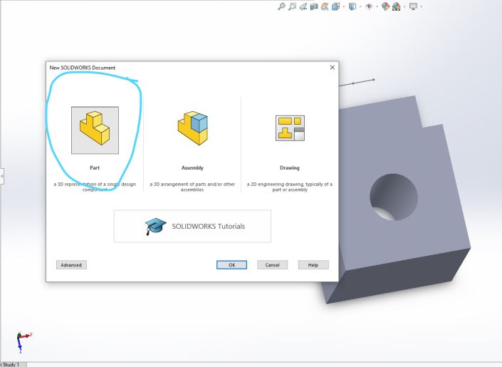
Create a new document and select new part.
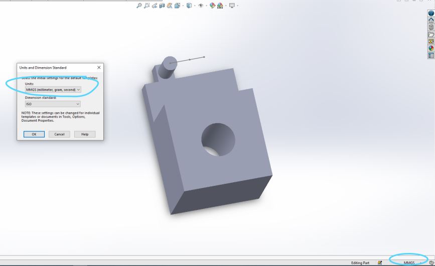
To change dimensions used on the component, click on the lower right of
the screen as indicated. For this component milimeters will be used.
Any modifications to a part or component can be measured using calipers
and directly applied to sketch.
After dimensions have been set, save your SOLIDWORKS Part (*.prt, *sldprt)
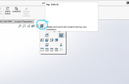
To begin it is important to be aware of the view icon shown. This icon
allows different views of sketches and 3D objects. Similarly, this can
allow the user to select different faces of an object to modify them
further.
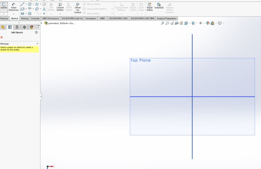
Once the sketch tab is selected there will be three planes that mimic
the x,y, and z planes. These planes can have sketches added to them.
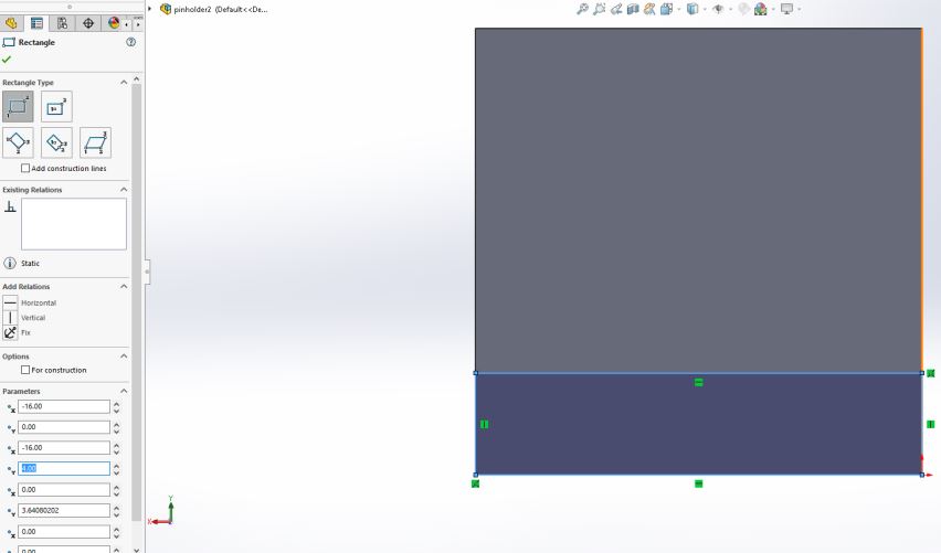
After selecting the top plane and the sketch icon there will be a
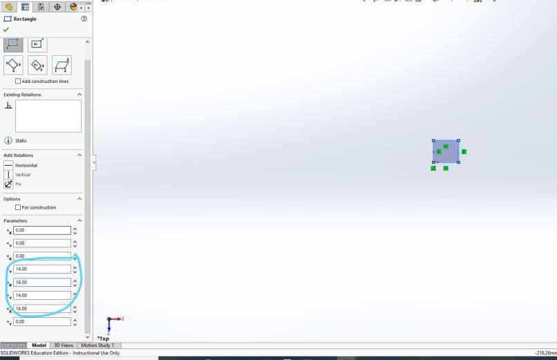
rectangle sketch icon, shown in the top left corner. This allows the
user to create rectanges and the parameters can be edited after a
rectange has been sketched. For the current example, the x parameter
has been set to 16(mm) and y-parameter 14(mm).
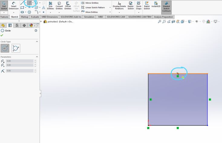
After the x and y dimensions have been set, click the circle sketch
icon shown in the top left corner. If the user drags the mouse over the
midpoint icon shown to the center of the square and similarly on the
side midpoint icon, then a center point can be found. The center point
is the place to click the mouse to begin to draw the circle.
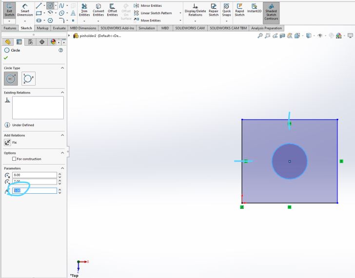
Once the circle has been drawn it can be modified using the parameter section on the left side of the screen.
Next, select the exit sketch icon on the top left of the screen.
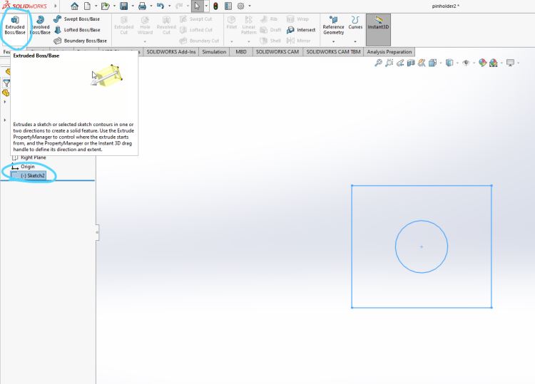
Once the sketch has been exited it will be appended to the left side
menu. Next, select Extruded Boss/Base icon shown in the top left of the
screen.
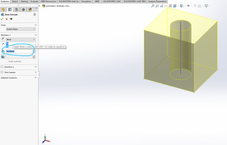
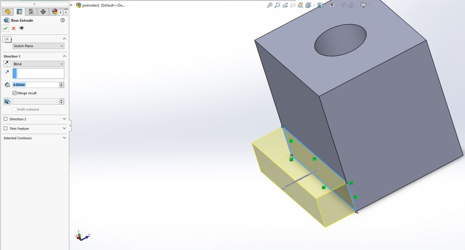
The Extrude Boss/Base function will allow the sketch to become 3
dimensional. In the example shown, the sketch has been extruded to
16(mm). Select the check mark to fully extrude the sketch.
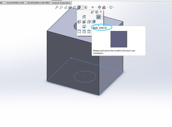
Now select the view icon shown in the center of the screen. Once selected, click on the back view icon.
With the back of the 3D object selected select sketch. This will enable
the user to sketch components on the back face of the object.
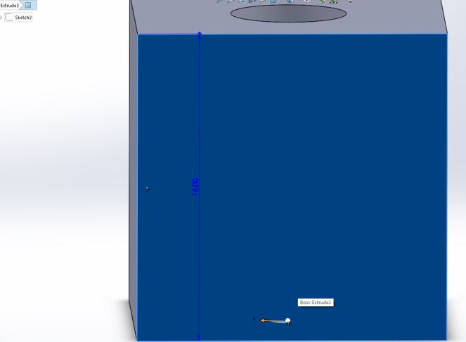
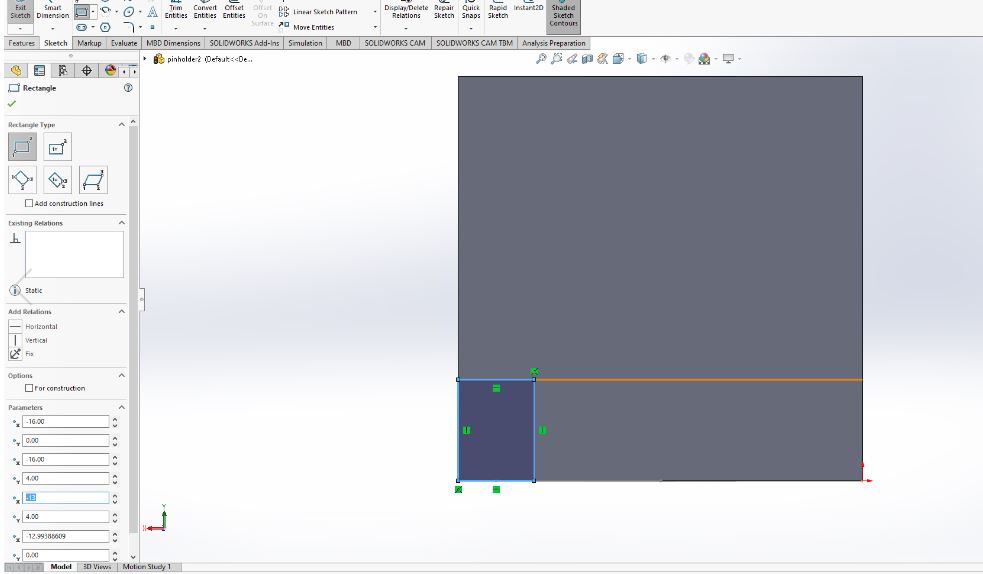
With sketch highlighted, select the sketch rectangle icon. Modify the
parameters to have a rectange of width 16(mm) and of hieght 4(mm).
With the sketch exited, the user can extrude the sketch to a length of 4(mm).
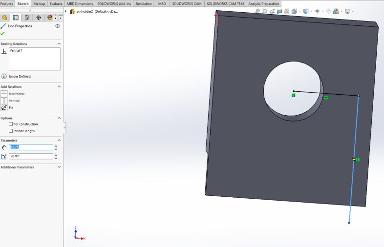
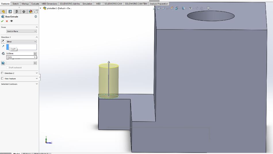
Now the tab has been added, toggle the view to show the bottom of the
component. We will build two reference lines by sketching on the bottom
plane. One line can be inserted by selecting the center of the circle
icon shown. The first line will be 6.75(mm) across and the second line
(connected to the first) will be 12.75(mm) toward the front face.
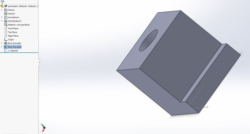
At this point the 3D component should look like this.
Now, select the front view of the component.
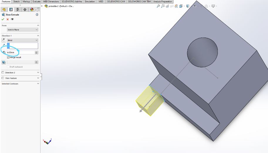
Sketch the rectangle shown onto the most outward face of the front view
or the tab constructed earlier. The sketch has been made flush with the
outward tab and given a width of 3(mm) just large enough to hold a pin
yet to be constructed.
Now exit the sketch and extrude the tab to 4(mm).
From the top view, the component should look like the previous shown.
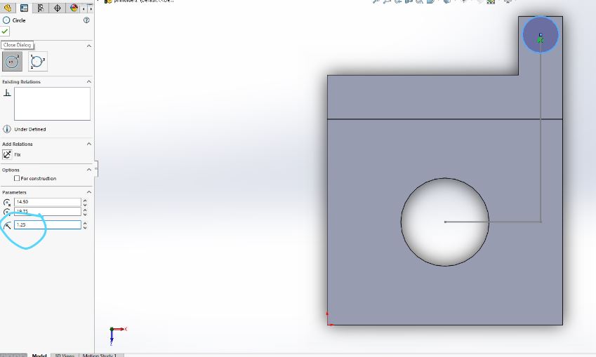
Now using the predefined lines it is possible to sketch a circle of
radius 1.25(mm). These lines can be deleted after but should not effect
the final print if left.
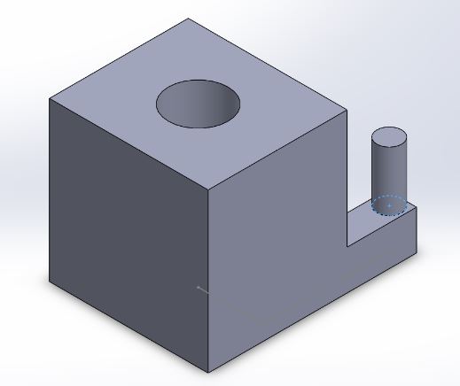
With the final circle sketch placed and extruded the final pinholder design has been constructed with in Solidworks.
Now, save the part as an STL file to then be uploaded into Cura software.
Once Cura is initally downloaded and opened the software will need to
know what type of printer is being used. The user will need to input
the type of printer so 3D components can be accurately printed.
Also different printer settings can be establish on Cura such as
various speed settings and heat setting, however, for the purpose her
the default settings are sufficient.
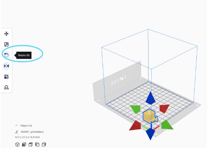
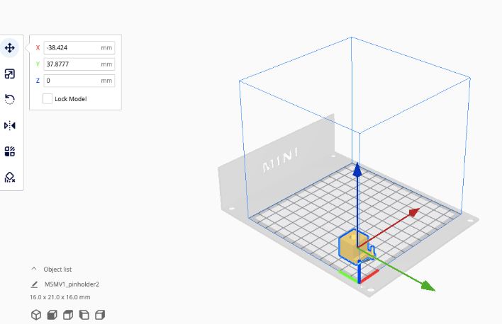
The component can be rotated on each axis to achive multiple orientations.
The component can also be positioned any where on the printer.
Generally the lower left corner is preferable. Once the position and
orientation has been modified the file can be sliced which means it
will be saved as G-code to be downloaded onto the 3-D printer.
Once the G-code has been downloaded onto a USB device capable of an
external SIM card (3-D printer only allows SIM card), the G-code can be
uploaded to the 3-D printer.
Before beginning the 3-D printing process the printer must be cleaned using a cleaning solution and paper towel. Also, the printer must be glued where the print will begin to avoid slipping of the 3-D printed component.
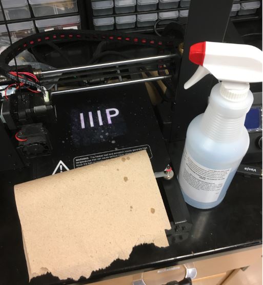
Once this has been done the print can be selected on the 3-D printer
screen and the printing process can begin. To turn the 3D printer on there is a switch located on the back of the hard drive.
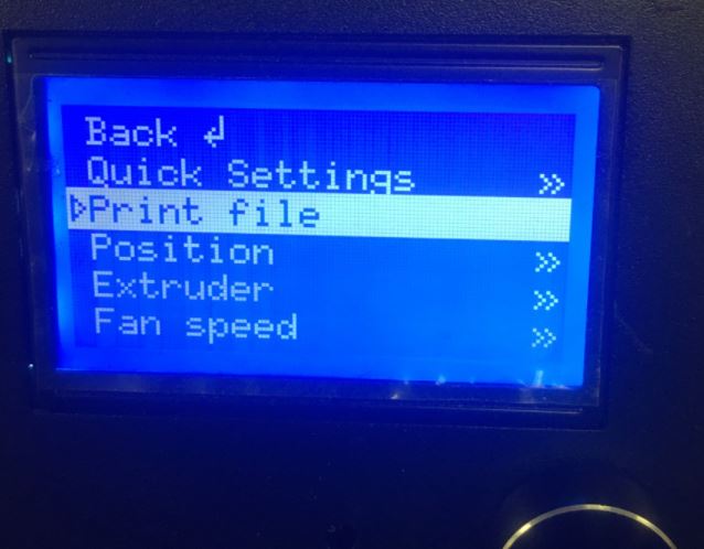
Once on the menu, the postion of the printer head and stage can be
changed. To print a file make sure the SD card has been placed into the
adaptor and select the print file icon shown.
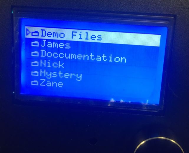
Go to the folder where the G-code was placed.
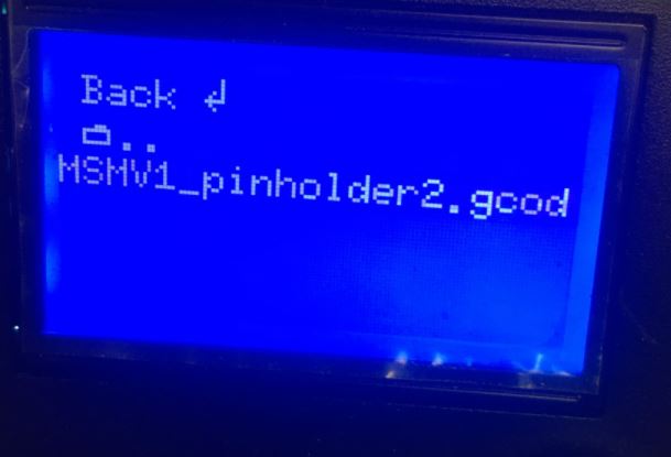
Select the G-code to start the printer.
Be careful when print is
done to not scrape the surface of the stage and use low angle to
dislodge the print.
Note- dimensions for other components of the Robotics II balancing
robot have been given so they can be constructed within Solidworks.
Conclusion:
The designs shown are for the balacing robot design in Robotics II.
These designs are not perfect and can always be improved using calipers
and Solidworks. The other components are a battery braket, a wheel
fitting, and lower brackets that mount onto the breadboard.