Softcore
Noah
Smith
In this softcore
assignment we will be using the picoblaze CPU adapted
for use on the 7 series FPGA chips. We will
us assembly language to write simple programs for this CPU to run.
Task 3:
Workflow:
The workflow
for this format of coding is vastly different from normal. It has 3 main steps
1.
Write
your assembly code
2.
Execute
assembly code with the compiler (kcpsm6.exe) in our case
3.
Generate
bitstream using Verilog CPU code and upload to the board
Below is a video
demonstration to show that I got this workflow working. It is a simple program
that maps each switch to an LED. Below is a picture of the Verliog
code used for this segment. The only thing that needs to be changed in this
code is the name of our compiled assembly code. This is at line 47, simply
rename this to whatever the new assembly
code is called.

Task 4:
Square Problem
This task
was to implement the square problem from the textbook, code and demonstration
can be seen below.

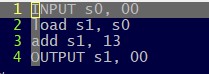
Task 5:
add 13
This task
was to add 13 to whatever the input was, code and demonstration can be seen
below.
Task 6: Using
a bitmask
This task was to use a bitmask and set the LSB’s to always be 11. We did this using an or bitmask which sets the bits.
AND bitmask: Saves bits
OR bitmask: Sets bits
XOR bitmask: Toggles bits

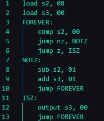
Task 7:
Shifting output
This task
was to shift the input 2 bits to the right and then display the output.
Assembly code and demonstration are shown.

Task 8:
Using Jumps
This task
was to get familiar with the jump commands and subroutines. Assembly code and demonstration
shown below.

Task 9: Test
Function
This task
used the test function to evaluate and compare values in the program, essentially
an if statement. Code and picture of result below


Task 10:
Comp Function
This task
was to get the same result as the test function but using the comp function
instead. Code and picture of results seen below.
Task 11:
Adding input
This task
was to write assembly code to count the number of input switches we had
flipped, then display that number in binary on the output LED’s. Code and video
demonstration below.
