LAB 3 part 1
Noah Smith
1. Complete the tasks in Sections 1.
Show your code, explanation, and demonstrate it in an embedded
video. (20 points)
Inverter, 2bit Full adder, 8 input AND gate:
The code for all 3 of these is in the same file, just separate
modules and uploaded to the board as one file. See the video for demonstration of
each in turn. The only thing to note is the Full adder code is just two of the
full adder codes from last week, spliced together with the first Co as the Ci
for the 2nd full adder.

4-1 MUX:
The 4-1 mux uses the same code as the week before, see the
video for demonstration.

2. Complete the tasks in Section 2. Show your code, explanation,
and demonstrate it in an embedded video. (20 points)
For my running LED demonstration I got
the original 4 LED code running at 1 second interval, but decided that was boring
so immediately changed the delay to ¼ second and made it run across all 16 LED’s

3. Similar to the example in Section 2, show running
LEDs on all 16 LEDs. Show your code, explanation, and demonstrate it
in an embedded video. (20 points)
In order to change how many LED’s flash
change this number:
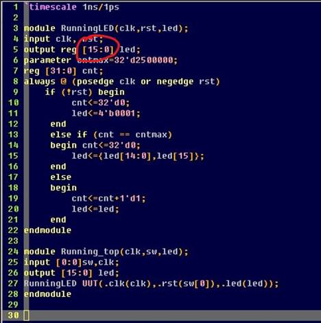
This affects how many LED you specify for the program to use.
Just remember to change it in the module and the TOP definition as well.
4. Similar to the example in Section 2, change the frequency of the 4 running
LEDs to half second and demonstrate it in an embedded
video. (20 points)
To change the frequency of the LED’s simply change this
number:

100000000 is a full second, so just divide by what you want the
frequency to be. Here is the fully demonstrated video with ¼ second frequency
and all 16 LED’s.
5. Complete the task in Section 3. Show your code, explanation,
and demonstrate it in an embedded video. (20 points)
Below is the code for the 7 segment
display that corresponds to the binary number that you put in on the switches.

Video demonstration: