ENGR 338 Lab 7 - Using Buses in Electric VLSI
Name: Max Krauss
Email: mtkrauss@fortlewis.edu
Intro: Within this lab, we will learn how to build a ring oscillator
and multi-bit logic gates using buses. Buses are defined by their
amount of lines, each line corresponding to one bit of data transfer.
In this lab we will be using 8 line data buses.
Task 1: Build and simulate a Ring oscillator. (20 points)
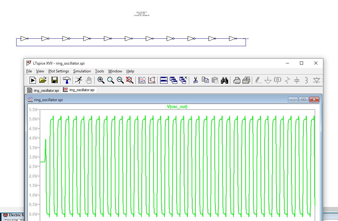
Figure 1.1: Ring oscillator built without buses and simulated in LTSpice.
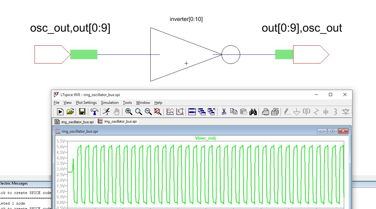
Figure 1.2: Ring oscillator built with buses and simulated in LTSpice.
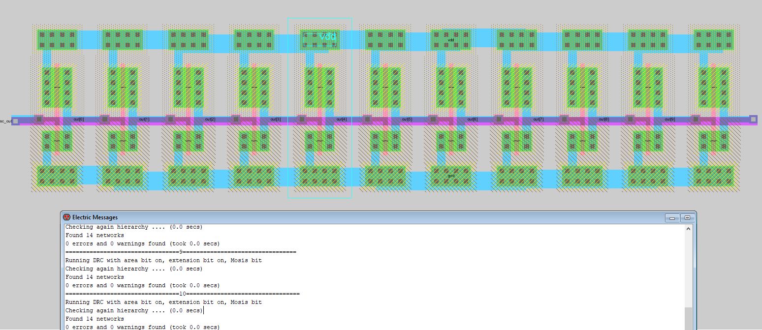
Figure 1.3: Ring oscillator layout with in Electric VLSI.
Task 2: Design an 8-bit AND gate. (20 points)
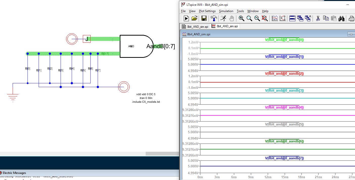
Figure 2.1: 8-bit AND gate built with buses (Simulation 1)
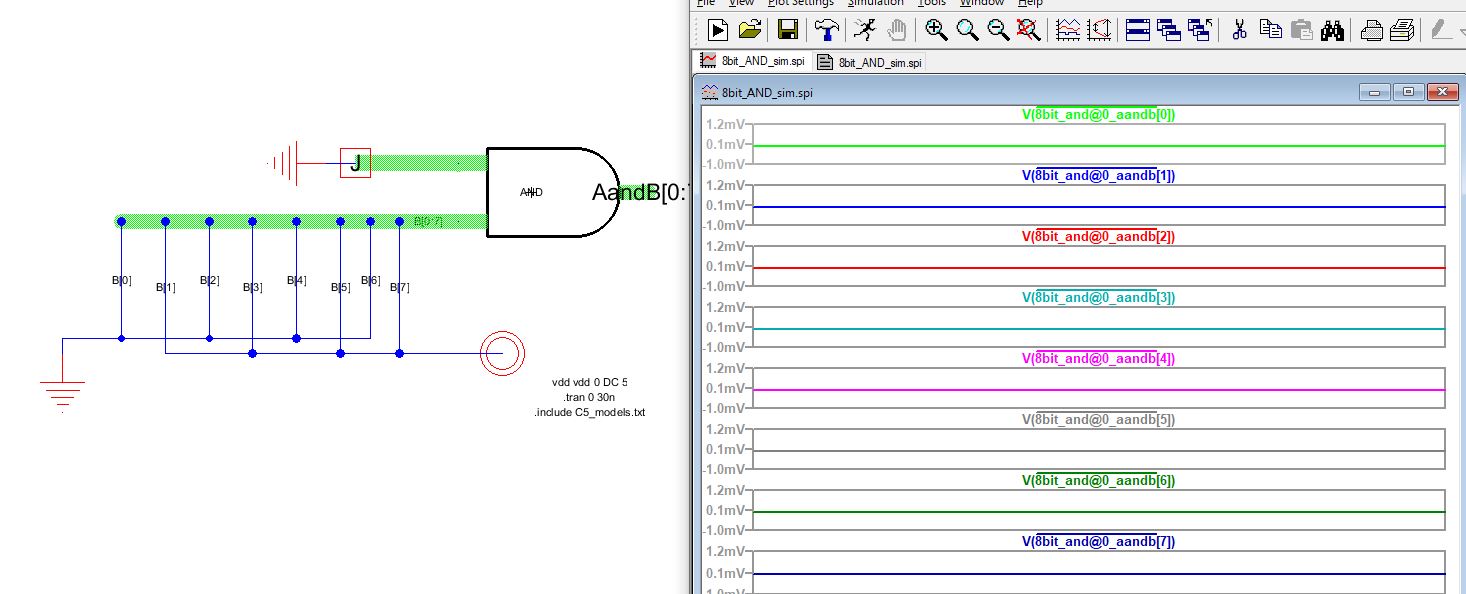
Figure 2.2: 8-bit AND gate built with buses (Simulation 2)
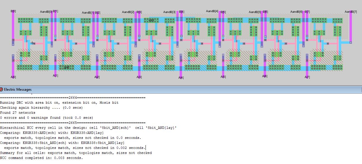
Figure 2.3: Electric VLSI layout of 8-bit AND gate built with buses.
Task 3: Design an 8-bit OR gate. (20 points)
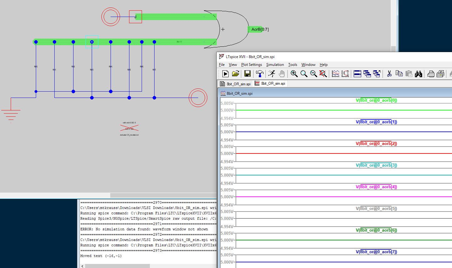
Figure 3.1: 8-bit OR gate built with buses (Simulation 1)
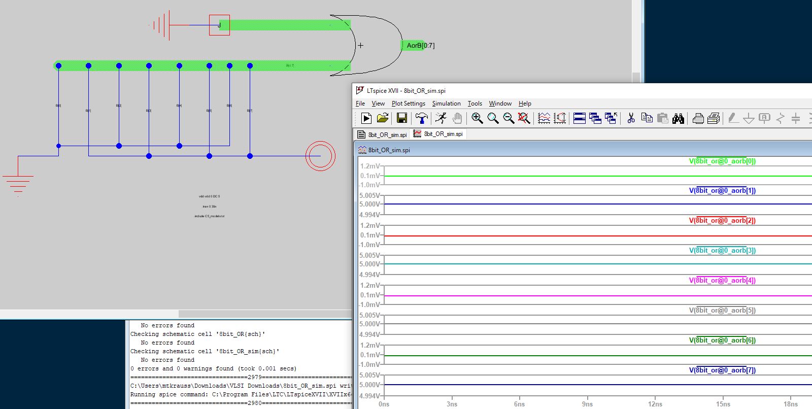
Figure 3.2: 8-bit OR gate built with buses (Simulation 2)
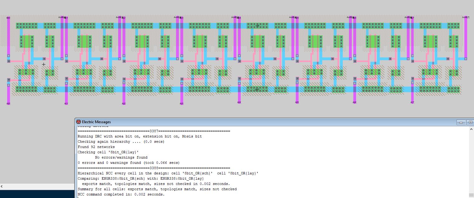
Figure 3.3: Layout of the 8-bit OR gate built with buses.
Task 4: Design an 8-bit NAND gate. (20 points)
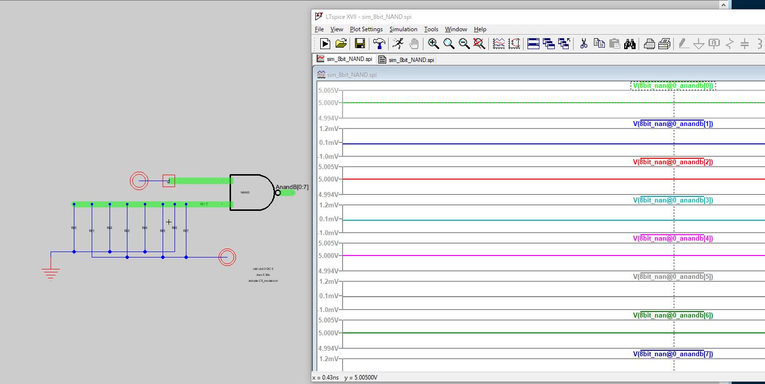
Figure 4.1: 8-bit NAND gate built with buses (Simulation 1)
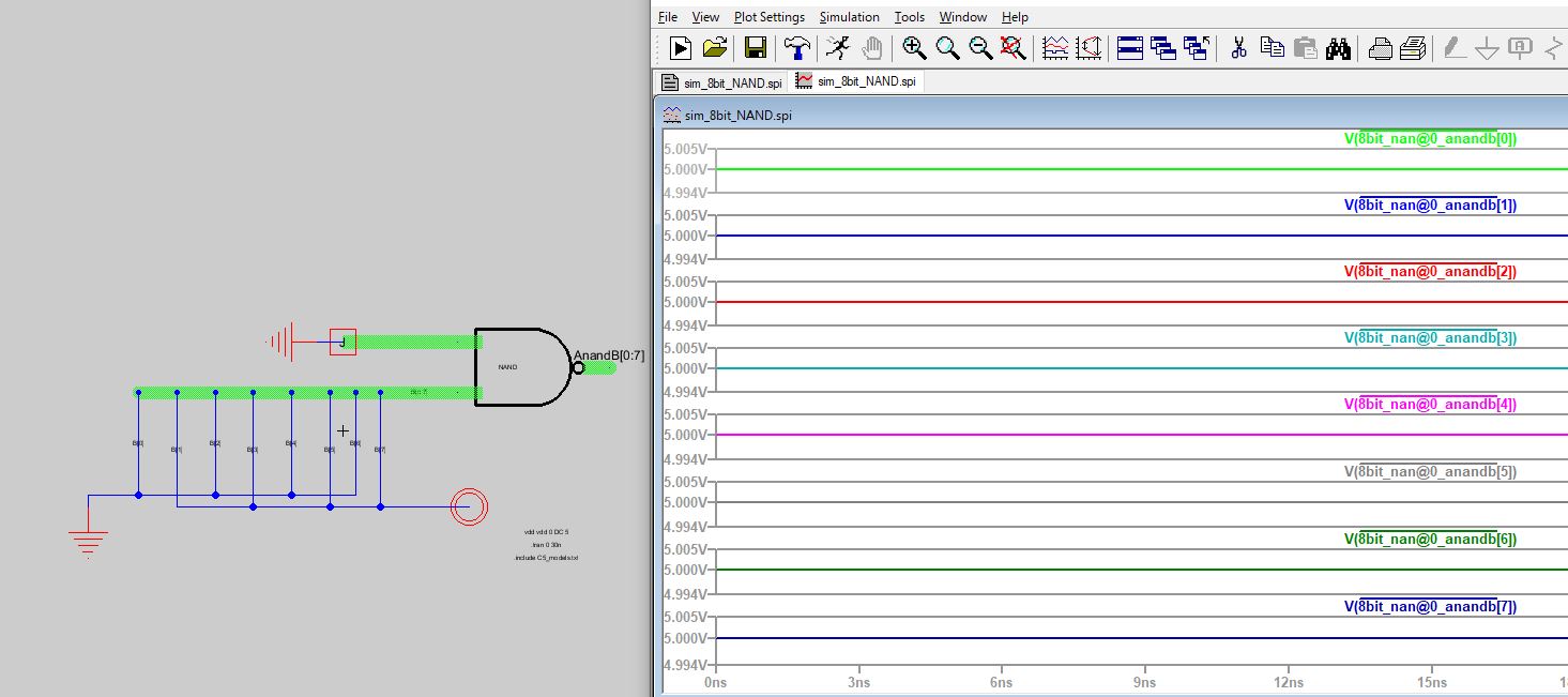
Figure 4.2: 8-bit NAND gate built with buses (Simulation 2)
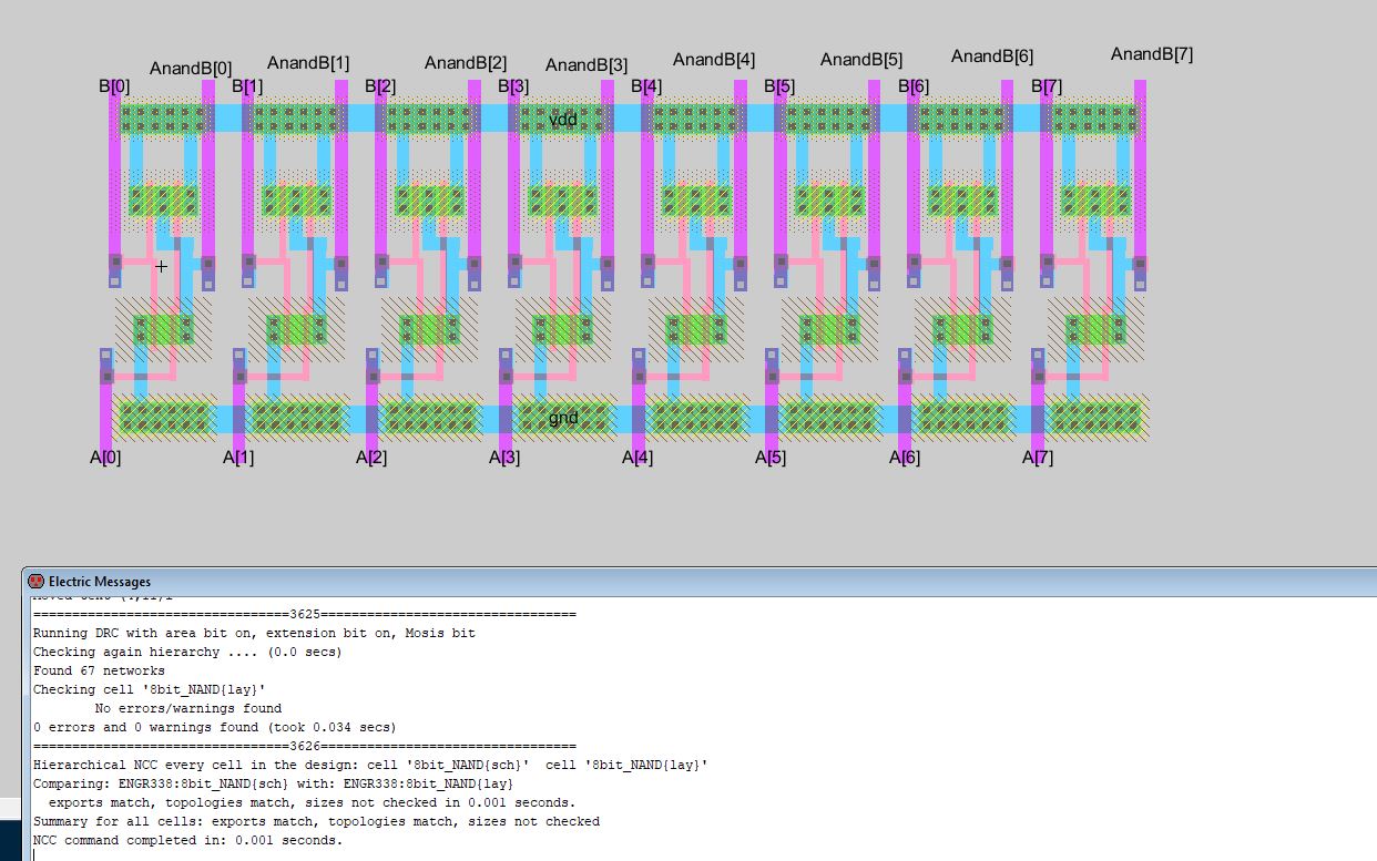
Figure 4.3: Layout of the 8-bit NAND gate built with buses.
Task 5: Design an 8-bit NOR gate. (10 points)
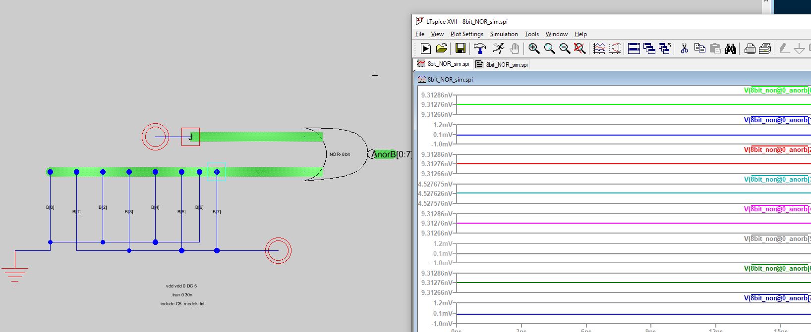
Figure 5.1: 8-bit NOR gate built with buses (Simulation 1)
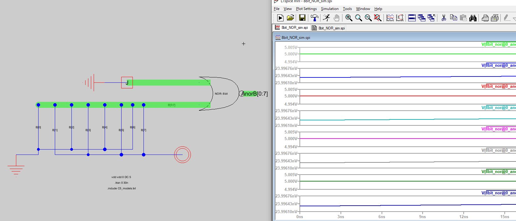
Figure 5.2: 8-bit NOR gate built with buses (Simulation 2)
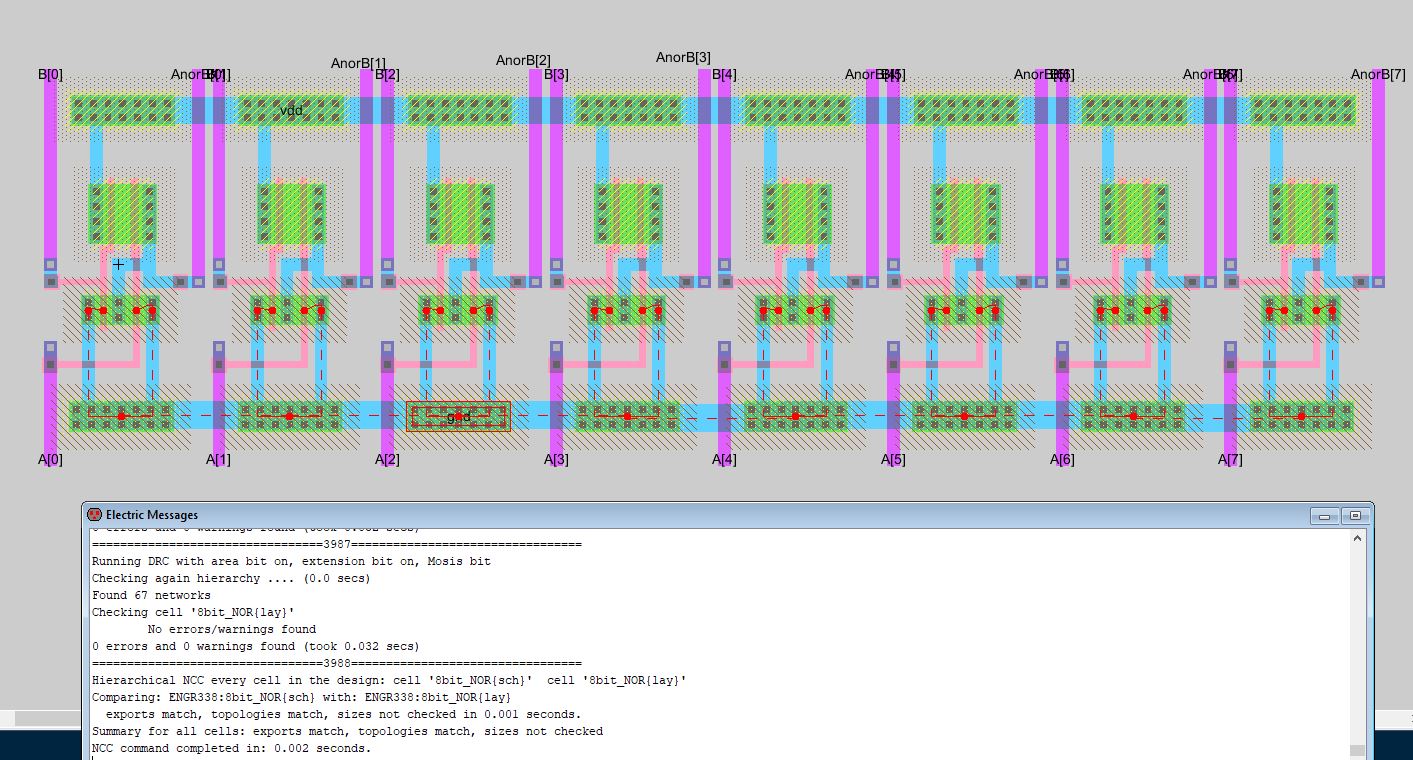
Figure 5.3: Layout of the 8-bit NOR gate built with buses.
Conclusion: This lab was a
great tutorial for learning how to utilize buses in Electric VLSI.
Buses are very important in computer architecture, as they connect the
internal components of the computer. Utilizing buses will be important
when constructing an 8-bit ALU.