ENGR 338 Lab 5 - The Invertor
Name: Max Krauss
Email: mtkrauss@fortlewis.edu
Objectives:
Be able to layout and simulate an inverter in Electric.
In this lab, we learned how to layout a 20/10 Invertor and a 100/50 Invertor.
** Task 1: Create the schematic of the inverter. (20 points)
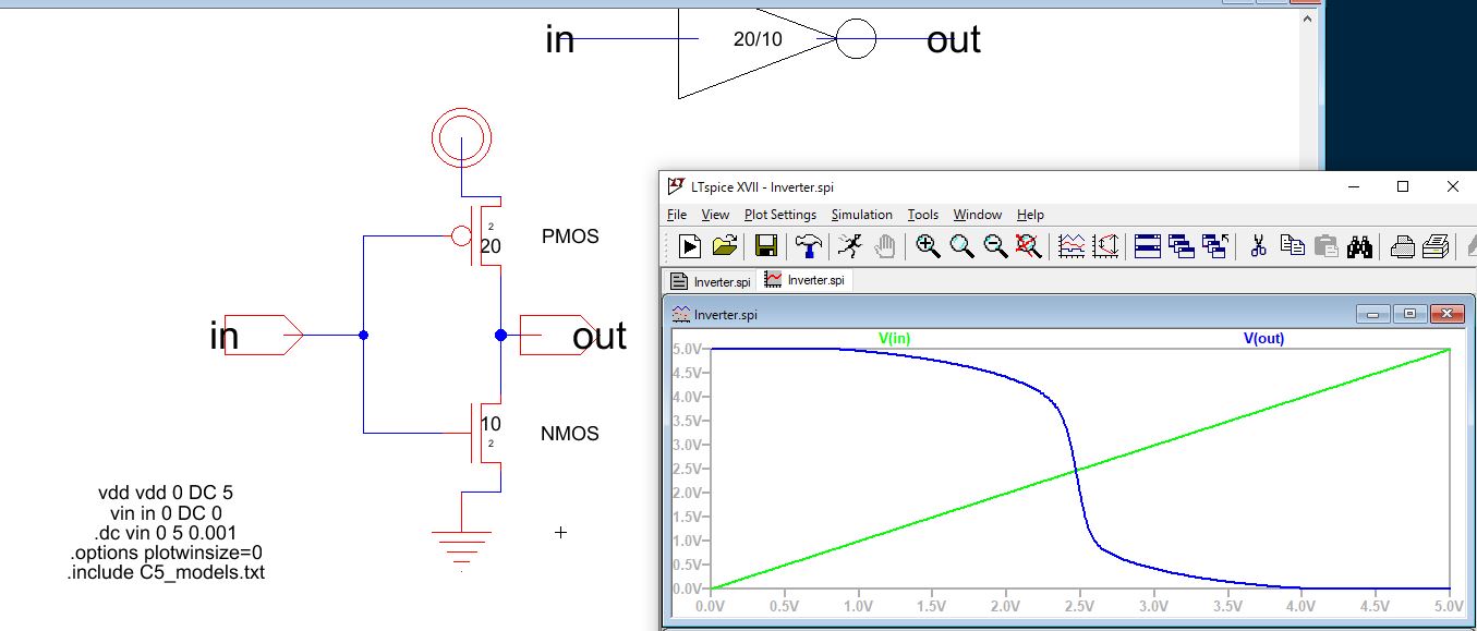
Figure 1: Schematic of the 20/10 invertor with a 0-5 volt DC sweep simulation.

Figure 2: Schematic of the 20/10 invertor with a 0-5 volt PULSE simulation.
** Task 2: Create the layout of the inverter. (20 points)
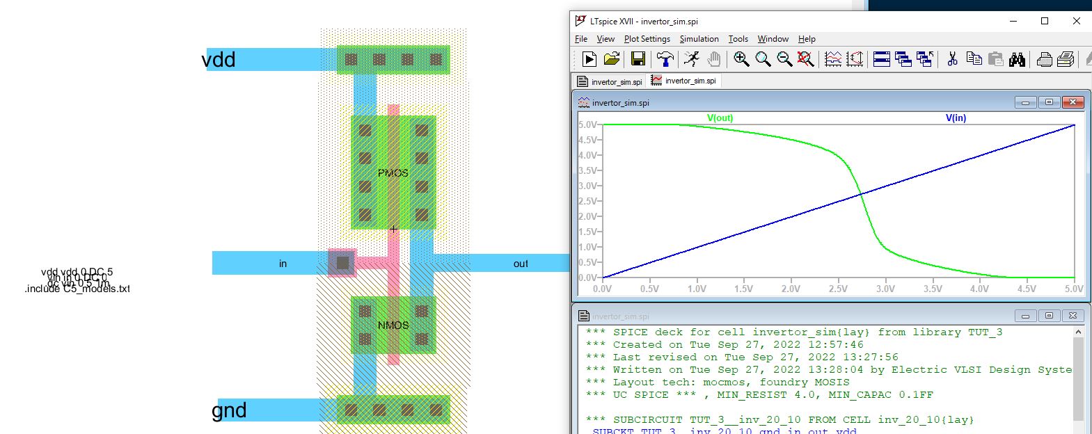
Figure 3: Layout view of the 20/10 invertor with corresponding 0-5v DC sweep simulation.
** Task 3: Use the multiplier to build a larger inverter. (20 points)
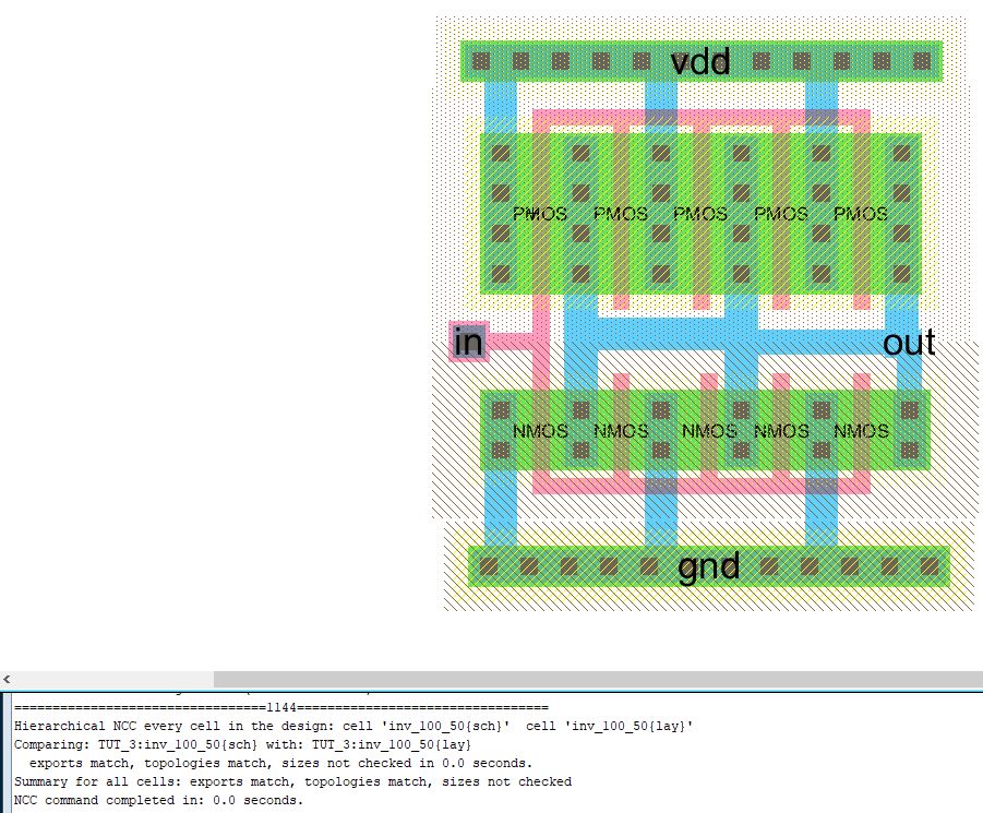
Figure 4: Layout view of the 100/50 invertor.
** Task 4: Run simulations to verify the driving capability of these two different inverters. (20 points)

Figure 5: Schmatic view of the 20/10 invertor icon with a 100f load capacitor. Simulated with a 5v PULSE wave in Ltspice.
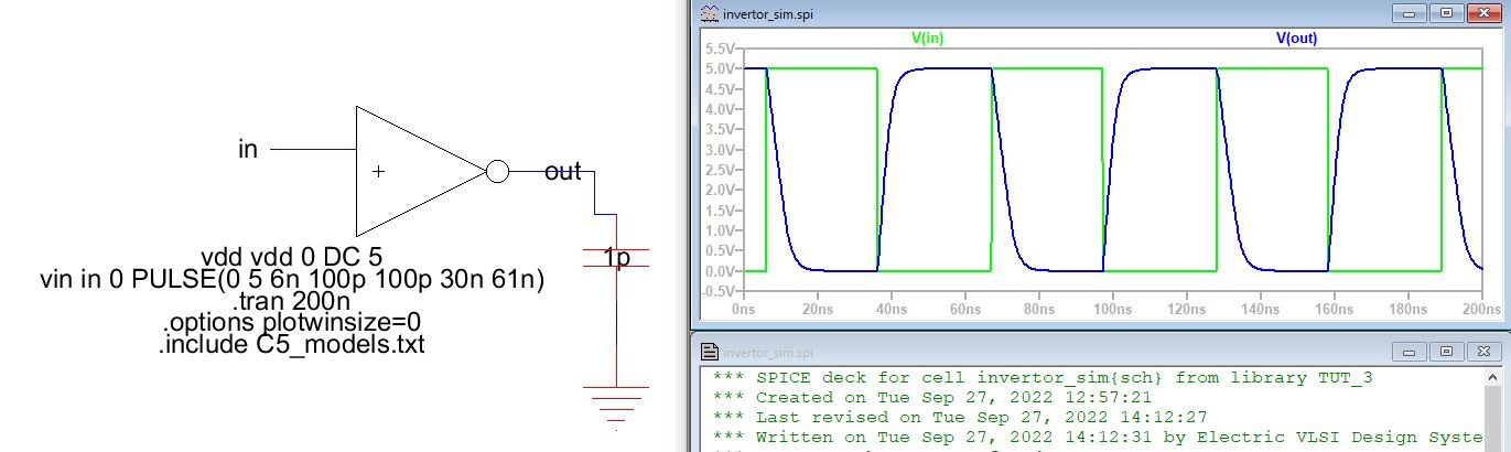
Figure 6: Schematic view of the 20/10 invertor icon with a 1p load capacitor. Simulated with a 5v PULSE wave in Ltspice.
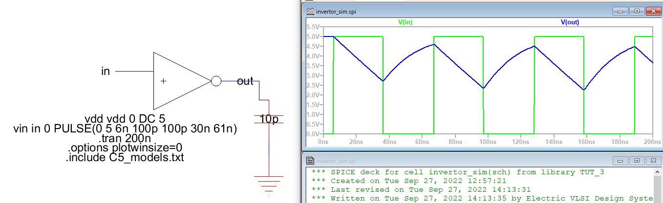
Figure 7: Schematic view of the 20/10 invertor icon with a 10p load capacitor. Simulated with a 5v PULSE wave in Ltspice.
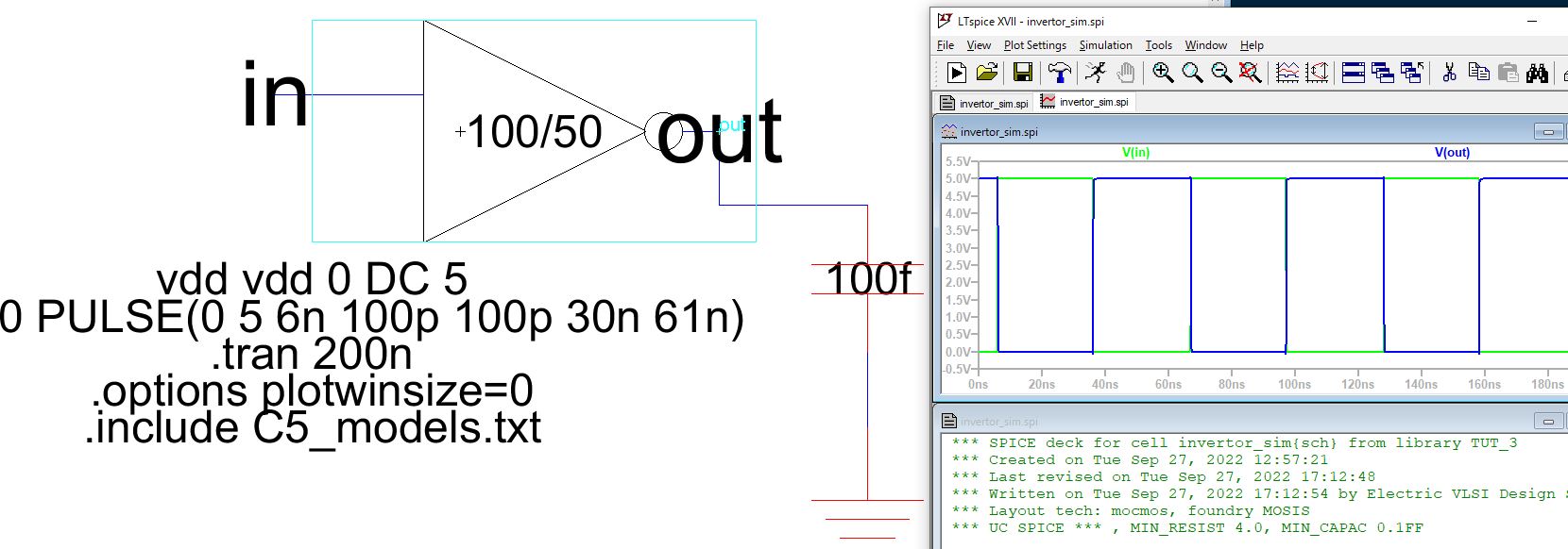
Figure 8: Schematic view of the 100/50 invertor icon with a 100f load capacitor. Simulated with a 5v PULSE wave in Ltspice.

Figure 9: Schematic view of the 100/50 invertor icon with a 1p load capacitor. Simulated with a 5v PULSE wave in Ltspice.
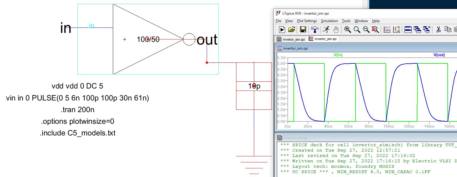
Figure 10: Schematic view of the 100/50 invertor icon with a 1p load capacitor. Simulated with a 5v PULSE wave in Ltspice.
Conclusion: This
tutorial was super cool to implement. We are beginning to see how
powerful Electric VLSI can be in designing ICs. It was satisfying to
see the layouts pass DRC and NCC and work as intended in the
simulations.