CE432-1 Robotics II 2021
Fall
Balancing Car project
Name: Mychael Garcia Email:
mhgarcia@fortlewis.edu
Materials:
Arduino UNO 2X
Analog Joystick
Open-Smart 2.4 GHz transceiver
USB data/power cabel
Breadboard
Jumper wires (M to M, M to F)
NEMA17 stepper motor 2X
A4988 Motor controller 2X
MPU6050 a three-axis accelerometer and gyroscope
Car frame materials (acrylic, nuts, threaded shafts, 3D printed components)
Introduction:
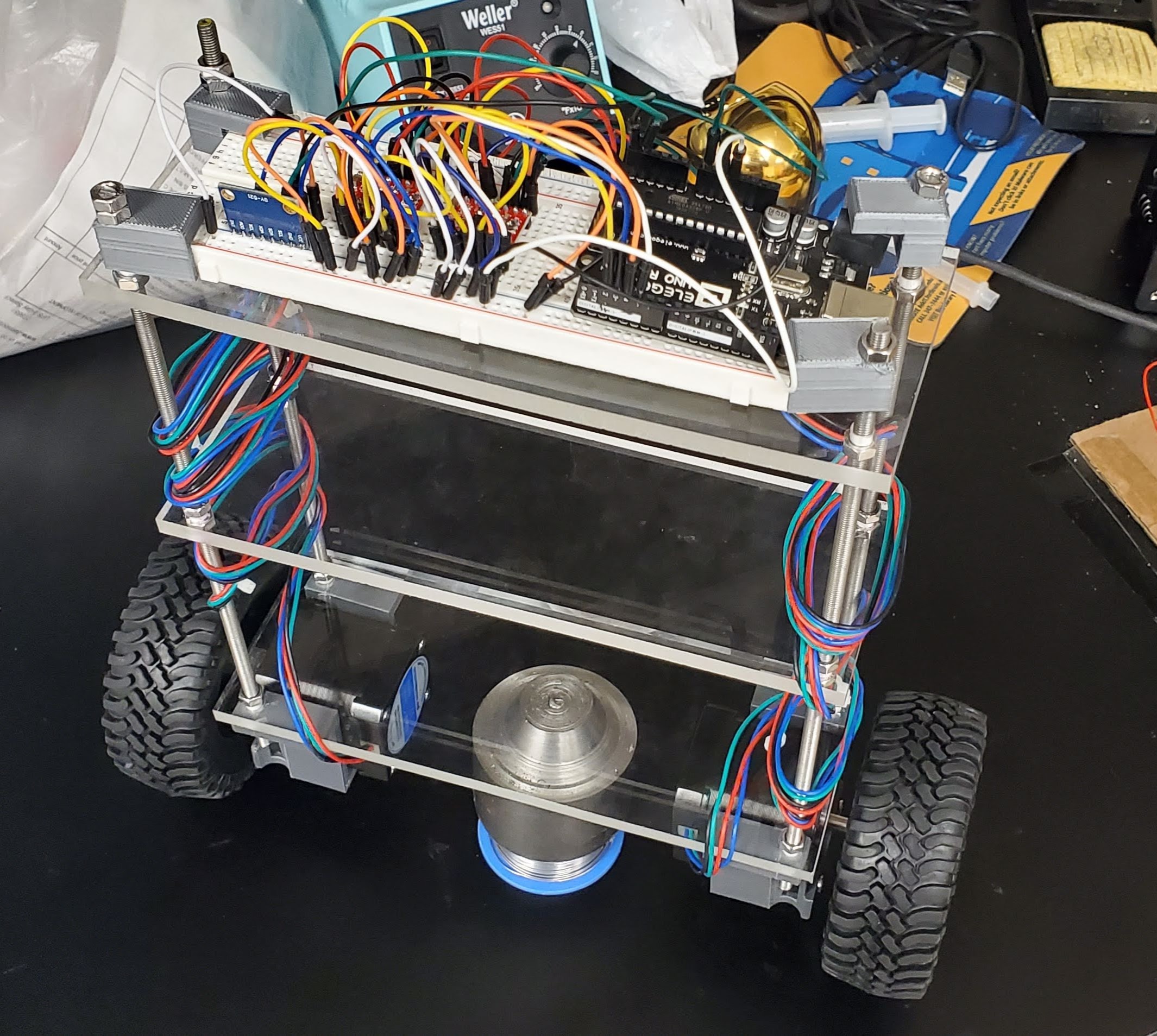
For this project, we were given the task of
building a 2 wheeled car that it is all self-contained and can balance on its
own. This task involved 3D printing, design skills, coding, and lots and lots
of testing/calibration.
Process:
This project involved everything that we’ve been
doing for the past few weeks, how to control a stepper motor, get data from the
MPU 6050, and have a code that times how long it takes for it to run and use
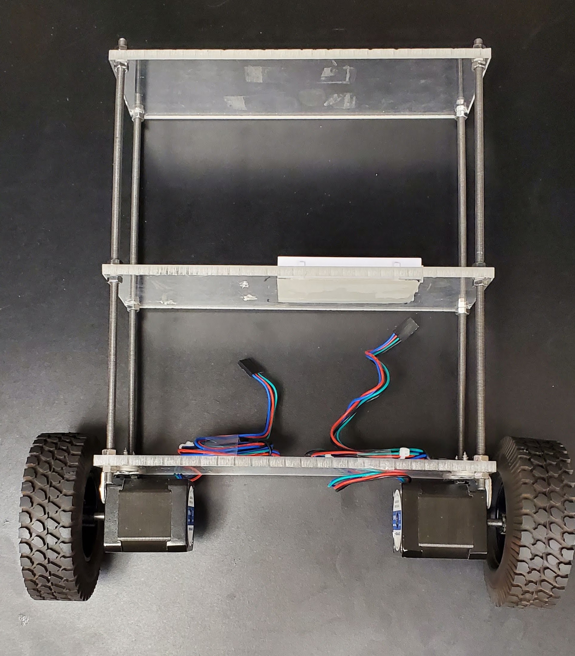
that in calculations. The first step was designing a chassis that all the
components would attach to. This was done by cutting an acrylic sheet into 3
8"x3" sections and drilling holes in each corner. Using a long-threaded
rod, this was cut in to 4 equal lengths roughly 10" long. Using nuts, each
rod was placed into a corresponding hole and secured. The end result was a three-level
frame that could be used to attach other components too.
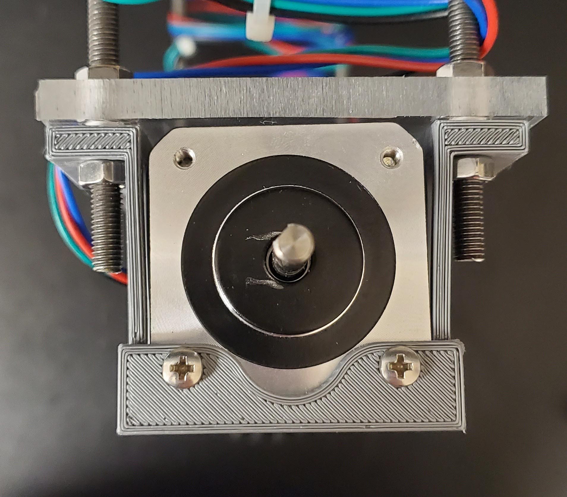
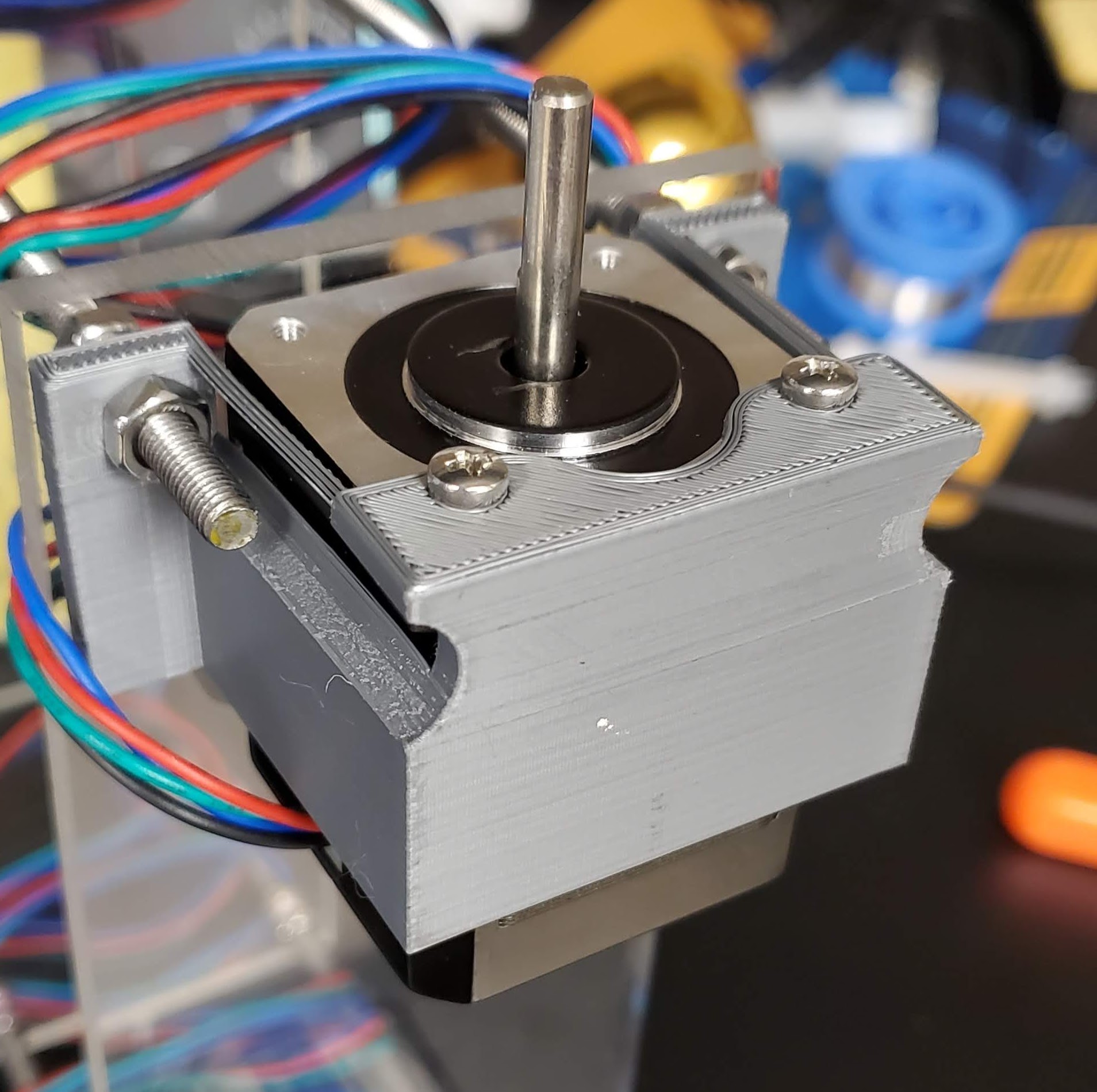
The second process was finding a way to mount
the 2 stepper motors to the chassis. This was done by 3D printing a bracket
that would wrap around the motor and have two screw holes to support the motor
so it would not slide around. The printer used was the Prusa i3 MK3S+ talked about in a previous project.
The STL file for these brackets can be found here.
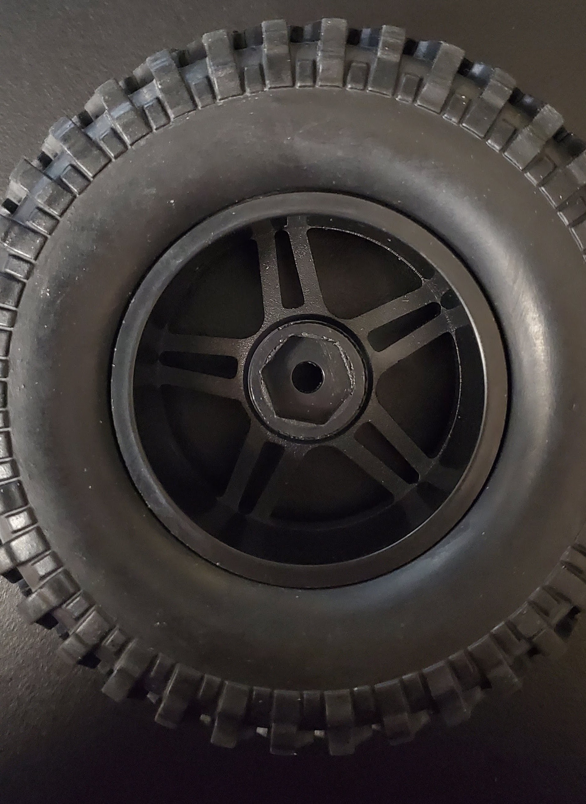
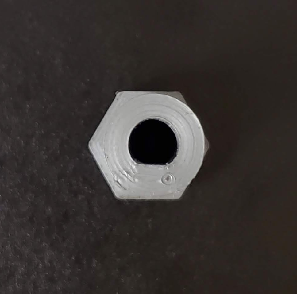
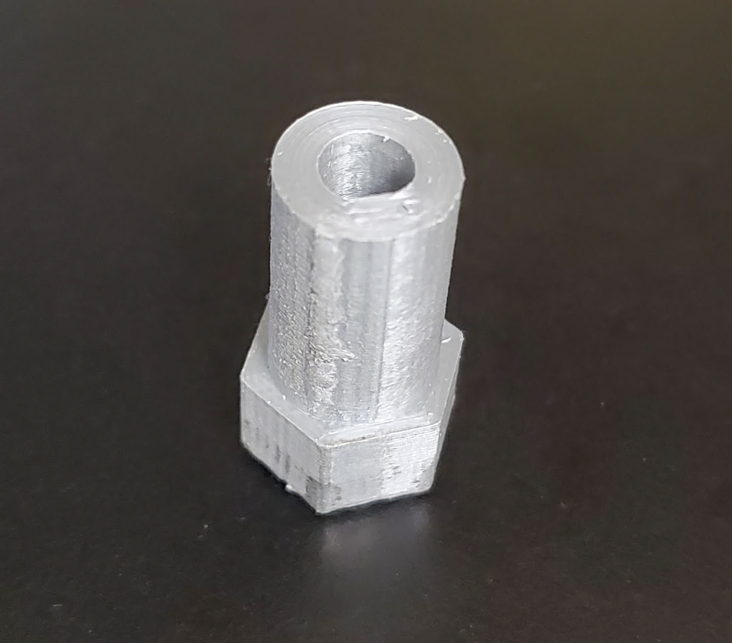
The third part also involved 3D printing. We need a
way to adapt the output shaft of the stepper motor to the wheels used in the
project. The wheels had a hexagon shaped hole that need to be mounted to the
keyed shafter of the stepper motor. To do this a small cylindrical part was
made that connected both pieces. The STL file for these adapters can be found
here.
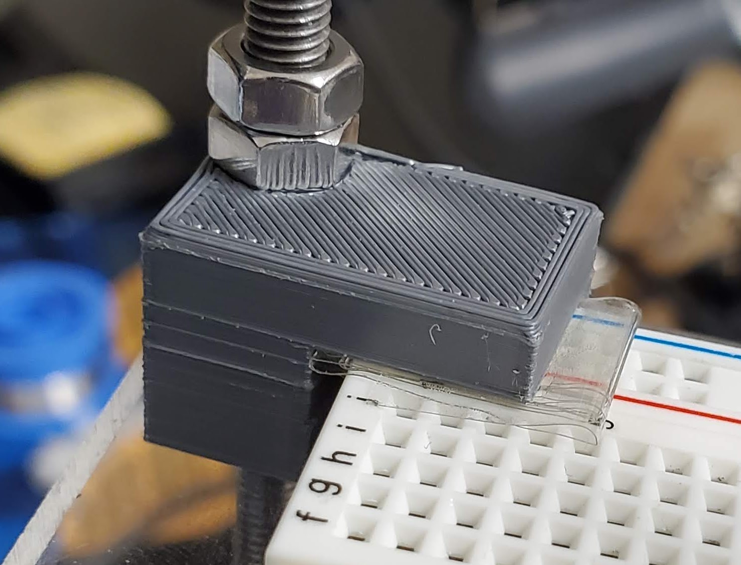
Fourth was a bracket to mount the breadboard and
Arduino to the chassis. This was also done using the 3D printer. The part had
small overhang and holes that could mount directly to the chassis frame. The
STL file for these mounts can be found here.
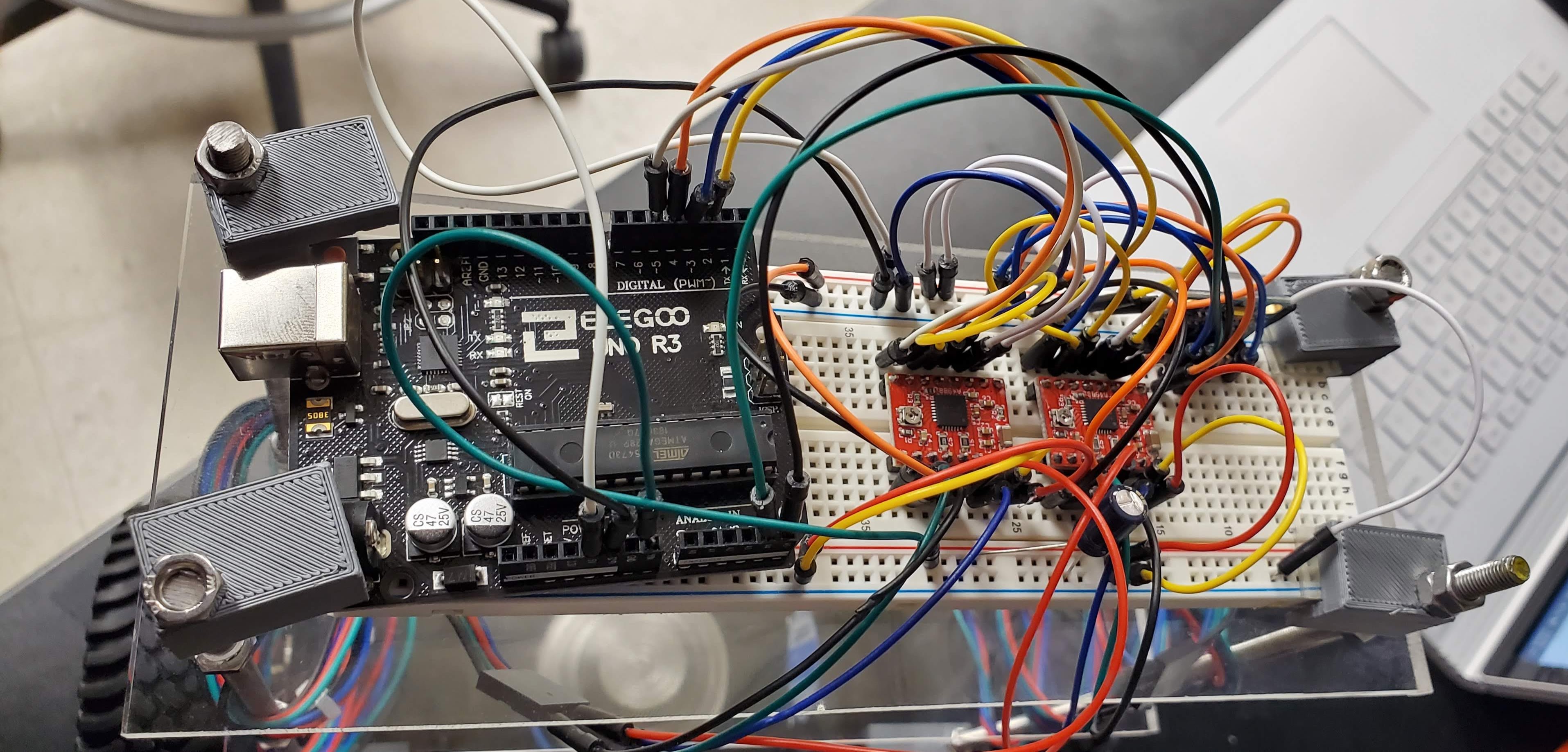
The fifth part was putting together and
programming the whole thing. This was the hardest part and took the most time.
The robot used an Arduino Uno to control the device, it would receive
positioning data from the MPU 6050 and in return send a signal to the motor controllers
to direct them on which way to turn to keep the car upright. The code for this
project can be found here.
After everything was connected, we started
programing it. This was the most time-consuming part. After calibrating the MPU
6050, we had to calibrate the PID controller. This is a rough calculation of
the error or change in angle of the car from its equilibrium state. Each error
equation had its own value, P=60, I=0, D=10. These values change how quickly
the motors accelerate to maximum speed. These values worked fairly well but one
con was that the car is extremely twitchy and tends to fall over easily with relatively
small angle changes.
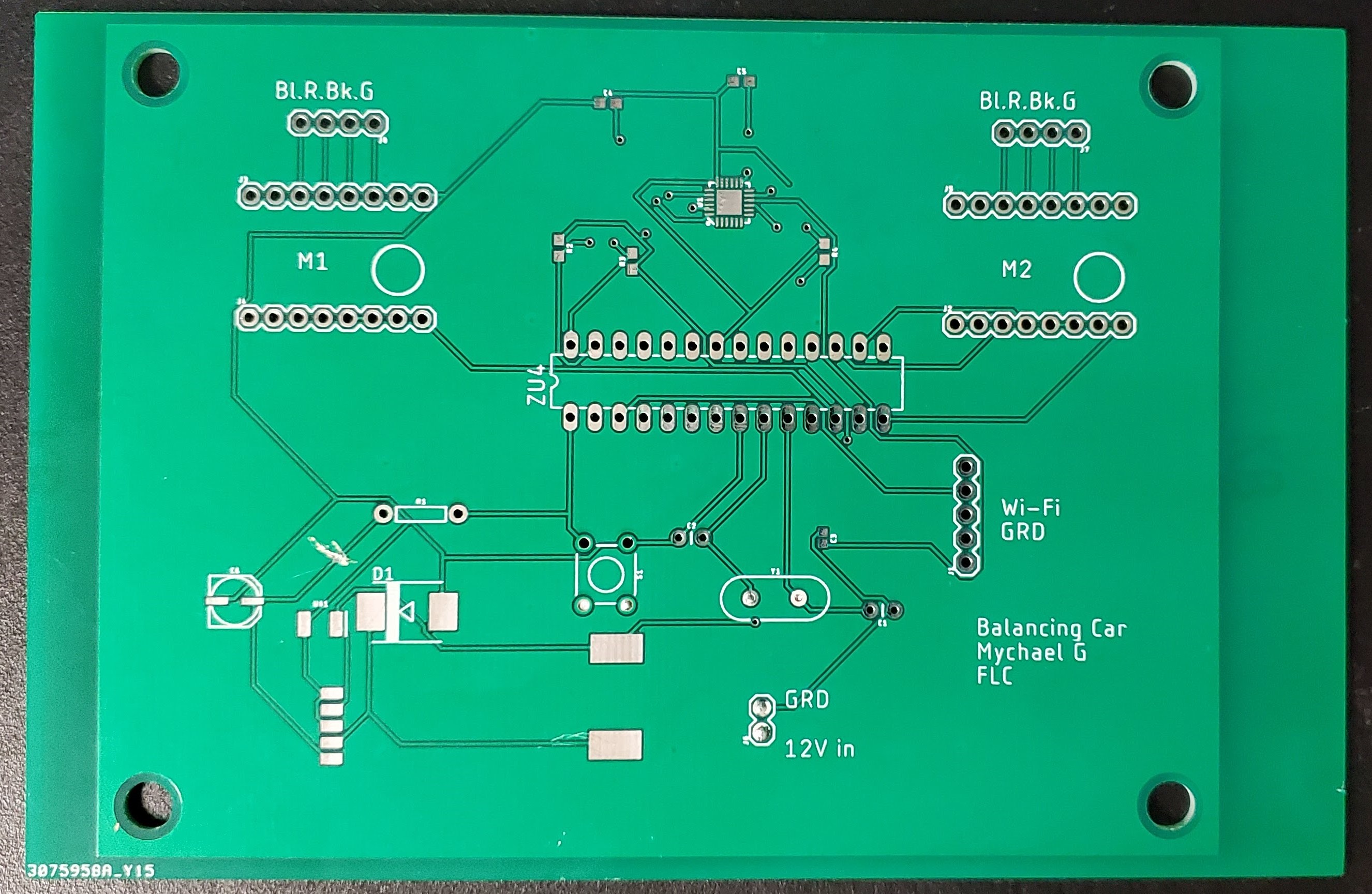
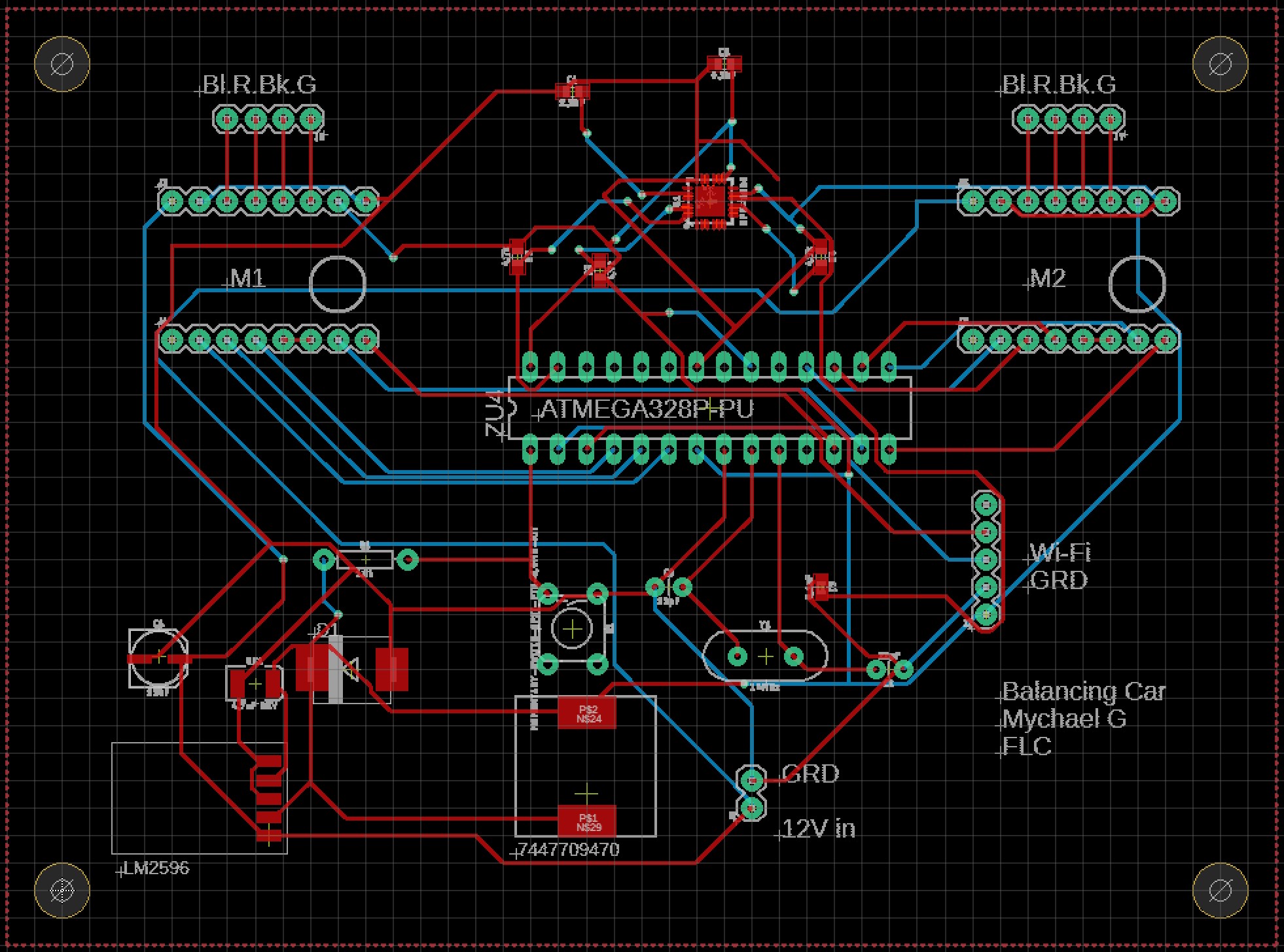
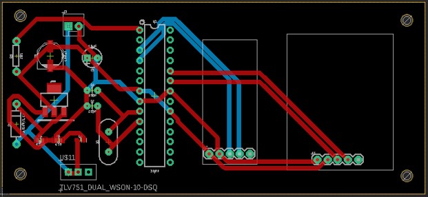
After
everything was running using the breadbaord the plan was to transfer
everything over to a custom PCB. As this was done before the cars were
running some initial guesses were made in how to connect the MPU-6050
chip and power the Arduino chip. As the PCB's take time to get made and
shipped we had to make them at the time we did. Knowing everything I do
now i would make changes to the PCB so it would be easier to use.
We
also planned on adding a remote to control the cars direction and
rotation. This was done by a partner in the class (Humberto Perez). It
worked well there was just not enough time to implement it into the
code as calibrating the car took longer than expected.
Conclusion:
This was a good
final project; you learn a lot about timing and more advance parts of programing.
Using the breadboard as a test run to make sure everything is working then
switching over to a PCB is a good idea, it does make it a bit harder to
calibrate as you have to use a second Arduino to get readouts of the first one.
This could be improved by adding a USB transcoder, but this would increase the wiring
and another point of failure. I wasn’t able to get the PCB and remote working
within time, but I was able to get the car to balance.