CE-351 Microcontrollers, 2022 Spring
Power Supply
Name: Mychael Garcia Email:
mhgarcia@fortlewis.edu
Materials:
EAGLE PCB
Various electrical components
Calipers
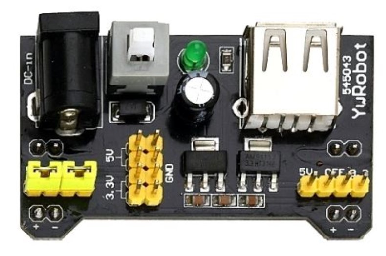
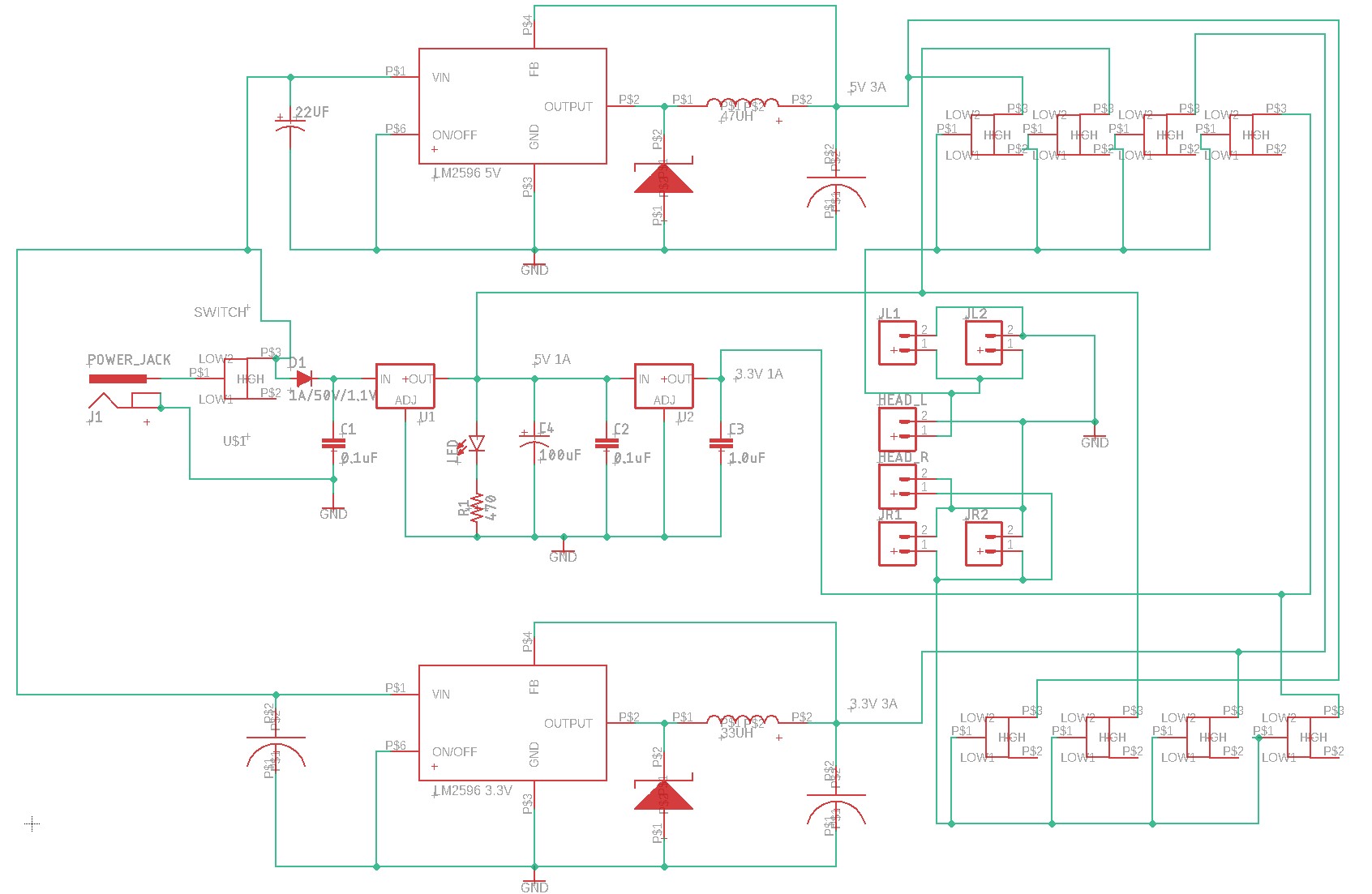
Power Supply Design: For this project, we were tasked with
creating/updating a 5V and 3.3V power supply. We were creating 4 output
channels that could be chosen from; 5V 1A, 5V 3A, 3.3V 1A, and 3.3V 3A.
1A designs:
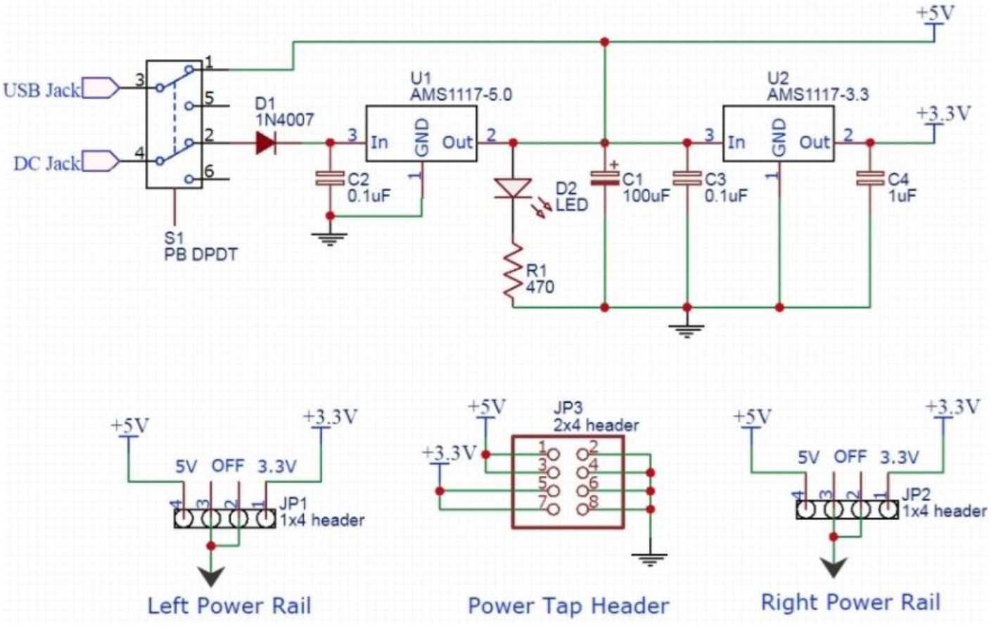
For the first task, we need to create a 3.3V and 5V design with a 1A current rating.
This simple circuit was based off of what is included in the Arduino developer
kit. Using the schematic we reproduce this on our board but with a slightly different layout. The reproduced version can be seen below:
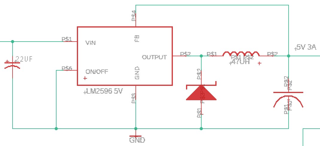
3A design:
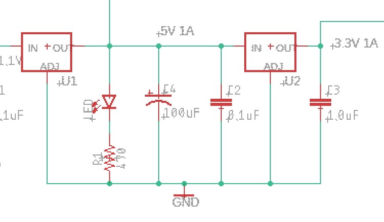
After building the 1A designs we created a 3A design. This was done using Texas
Instruments LM2596 and schematic builder. Using their schematic design tool we
were given a list of needed components, comparing these to ones provided in the
lab we had to create our own Eagle reference parts and electrical connections.
The LM2596 can be seen below:
Our rebuilt 5V 3A design can be seen below
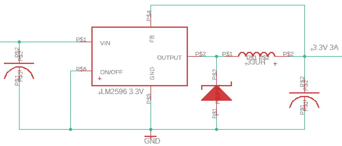
The same process was then used for designing the 3.3V 3A design
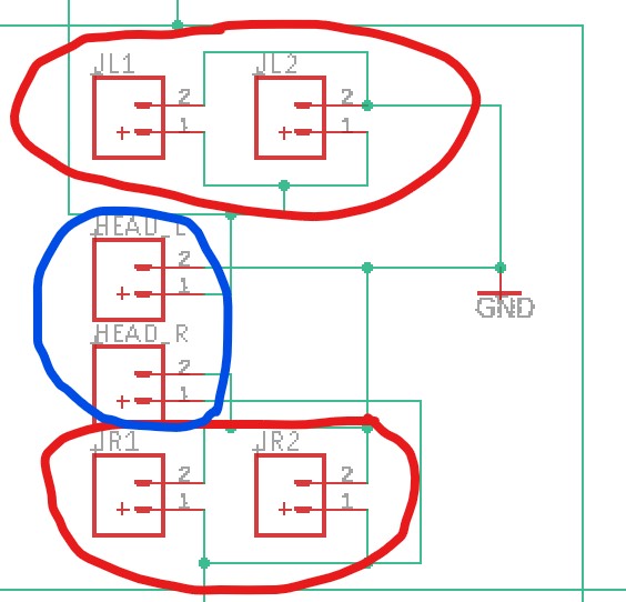
Connections and Power Output:
After devolving how were going to get the four output options. We need to develop
a way to output this to the breadboard and have the option to select which
power option we want to use. For connecting to the breadboard were going to use
2 sets of mail headers to connect to each side’s "power" rails (Red
outline). In addition, I added a set of female headers that don’t connect to
the breadboard and can have a direct connect using male cables (Blue outline).
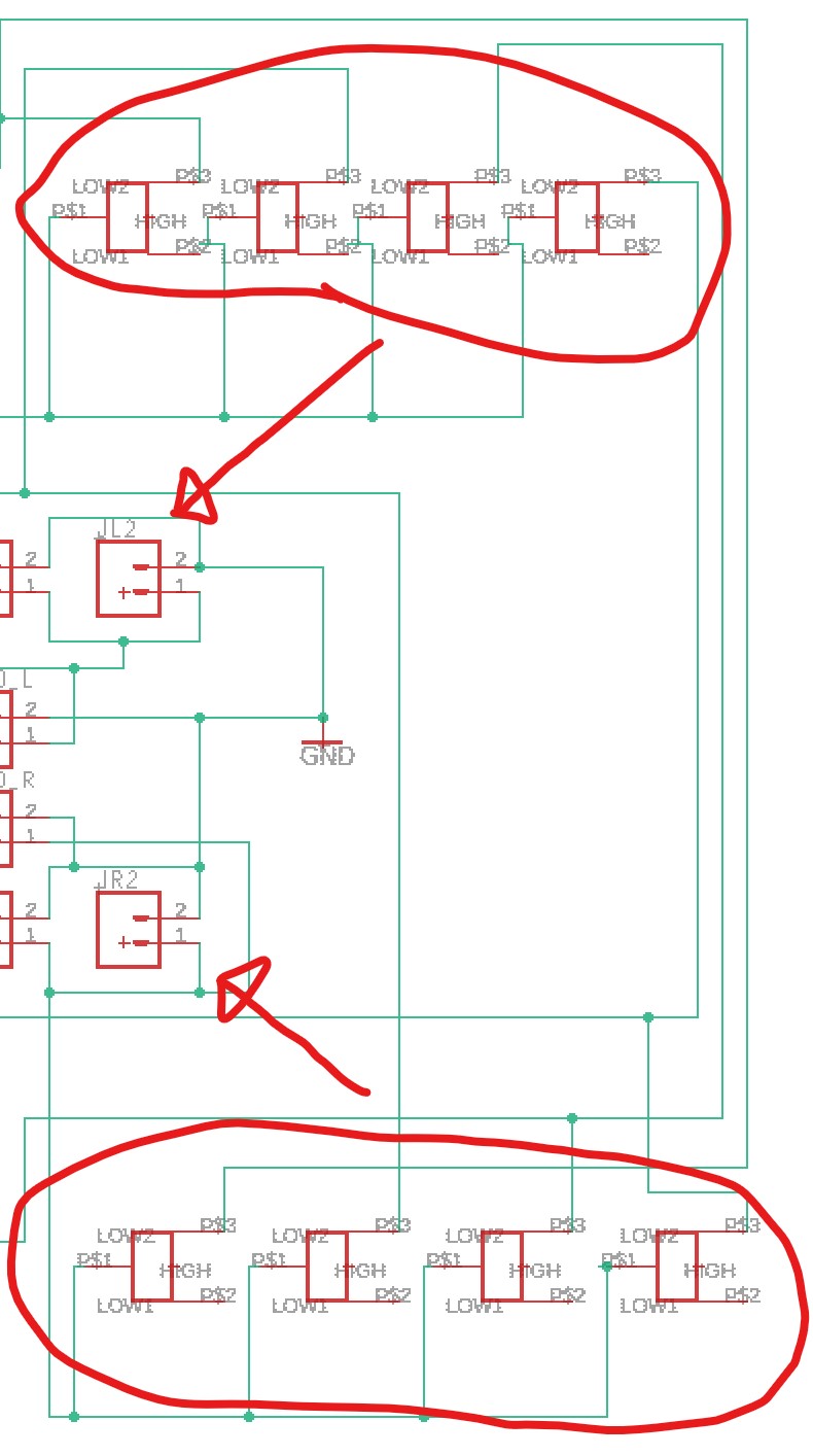
Power output selection: The
next step is to devolve a way that each rail can have its own power
requirements and that we can select which one we need to use. This was
done by adding 8 switches, 4 for each side, 1 for each power option.
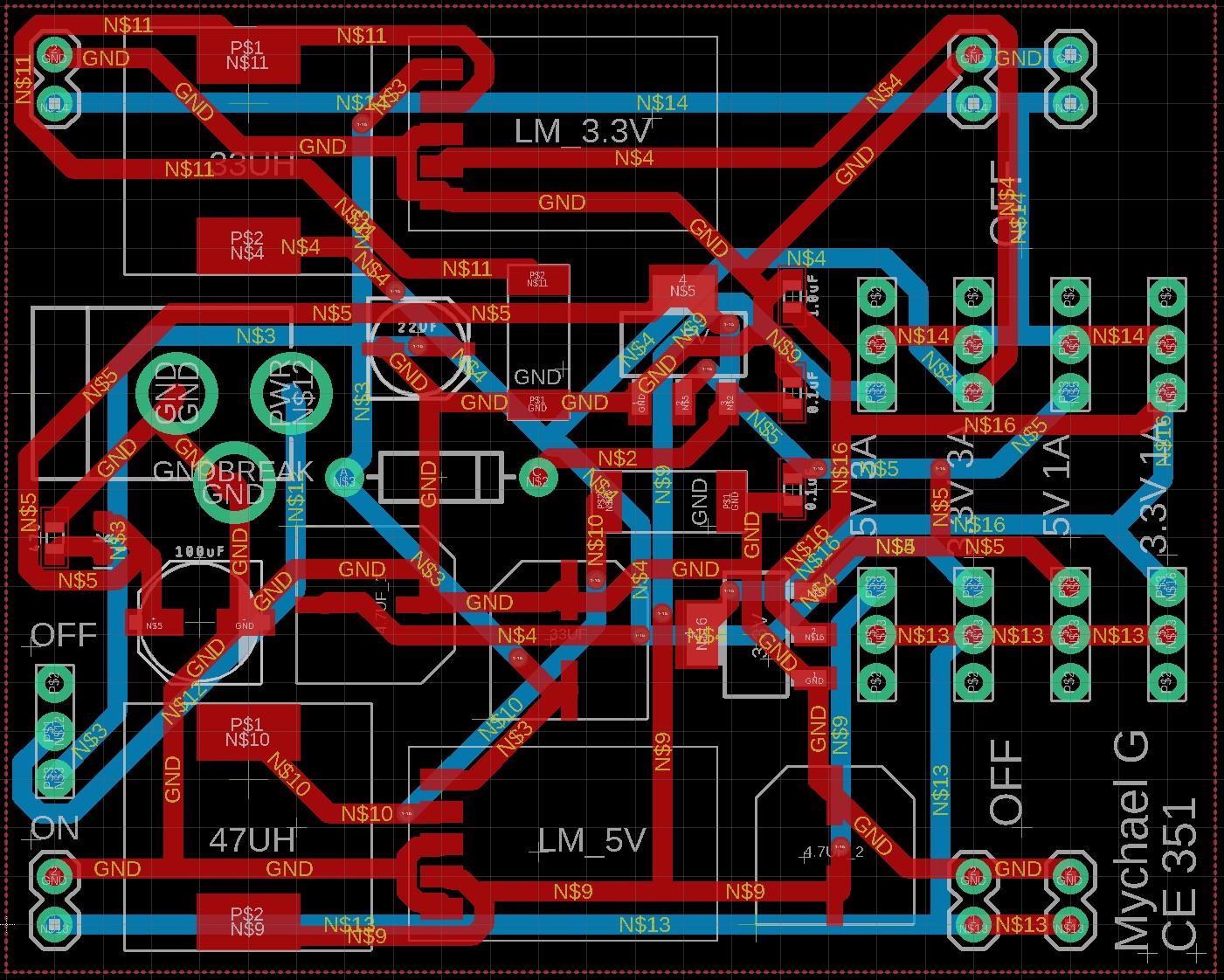
Final Layout and Manufacturing: The
final step was to lay out all the components onto a board and design a
PCB that can wire all of the connections for us. My final design can be
seen below:
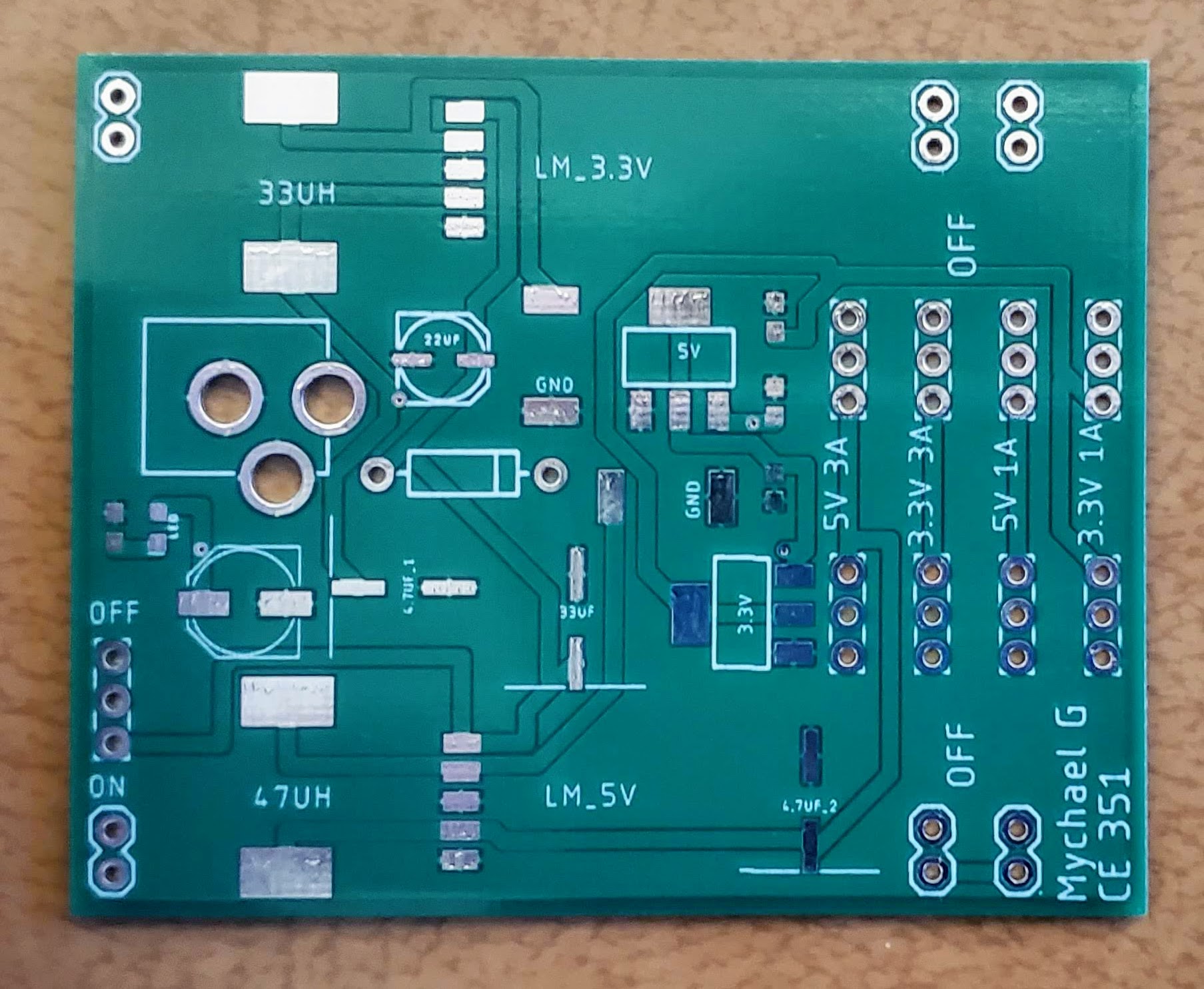
PCB: Receiving the PCB I verified some of the major connections and there were no
issues.
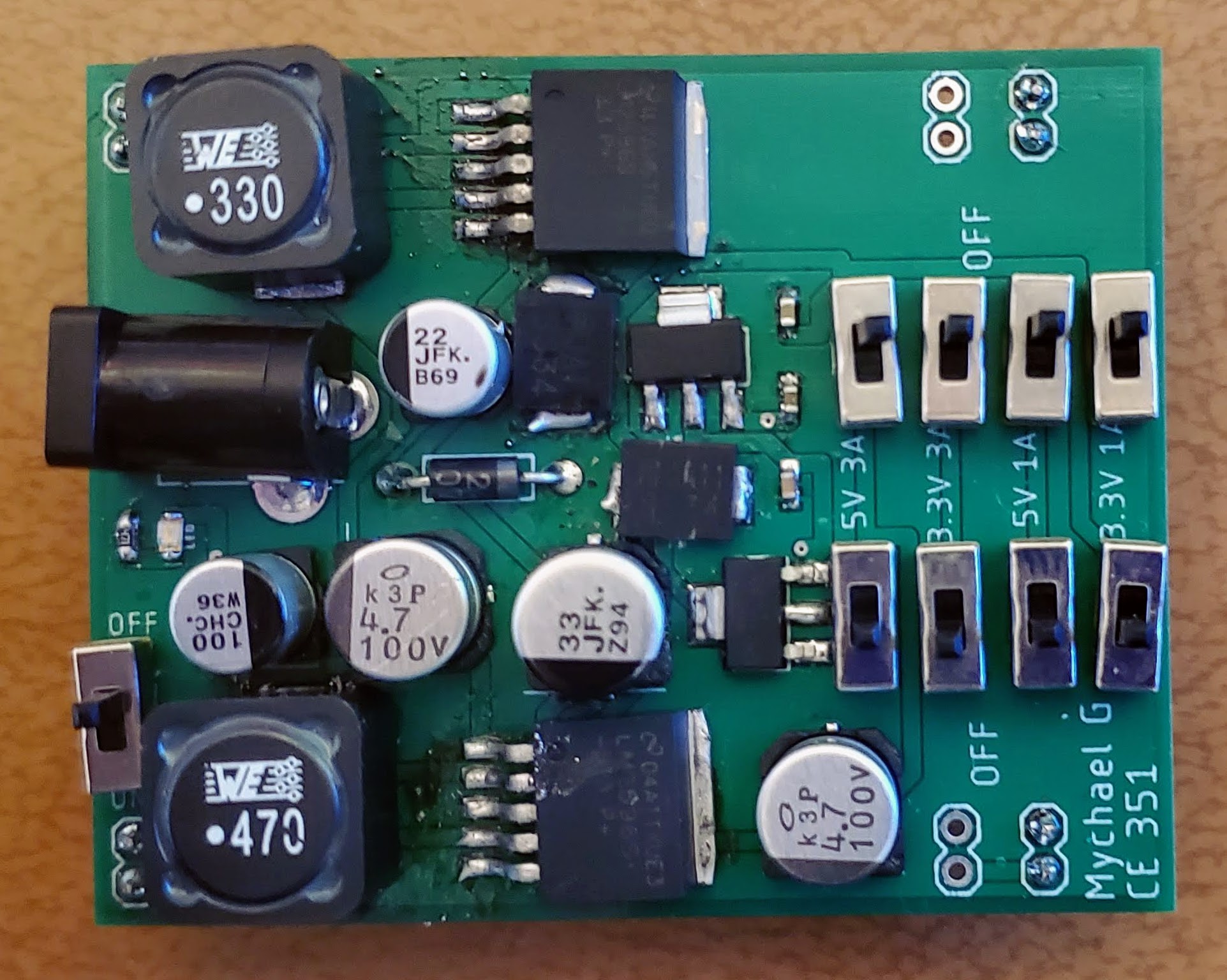
Soldering
components: After testing the PCB we
soldered all the components on. the hardest parts to solder were the Caps and
the LED, the connections for the caps are on the underside so it’s a little
difficult to heat the solder up and then place the cap on before it cools. The
LED is small enough that’s it’s hard to see the small green bands on it to symbolize
the cathode (negative) side.
Conclusion: Overall
this was a very useful and practical project that can be uses in everyday life.
For many Arduino projects the included power supply and built in one on many
Arduino boards is not enough. Thats where this comes in with its maximum supply
current being 3A it should be able to power all accessories. ---------------------------------------------------------------------------------------------------- END