CE432-1 Robotics II 2021
Fall
Joystick control
Name: Mychael Garcia Email:
mhgarcia@fortlewis.edu
Materials:
Arduino UNO 2X
Analog Joystick
Open-Smart 2.4 GHz transceiver
USB data/power cabel
Breadboard
Jumperwires (M to M, M to F)
NEMA17 stepper motor
A4988 Motor controler
Joystick controll: For this project we used
the Arduino UNO, analog joystick, 2.4 GHz transceiver, and stepper motor to wirelessly send signals to a second Arduino UNO. One board would record inputs
from the joystick and use the serial interface and send them to the
transmitter. The second board would use its own transceiver and send
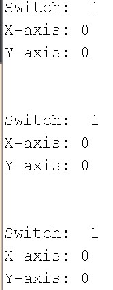
the values to the Arduino and print the values to the serial monitor. Later, a stepper motor was added to visualize the results. Task 1: For
the first task we were asked to take the signal from the joystick and
print the results in the serial monitor. This worked well as the
joystick had 3 functions; a potentiometer for the x-axis, a
potentiometer for the y-axis, and a button that would activate if the
entire joystick was pressed. The switch would display a 1 if it was
pressed or a 0 if it wasn't. For the x and y axis, they would be
displayed as a number between 0 - 1023. 1023 is 2^(10)-1, this is the
maximum bit rate of the Arduino (10-bit). If
the joystick was pushed down and to the far left, for the x and y axis
respectfully, the numbers would display values close to 0.
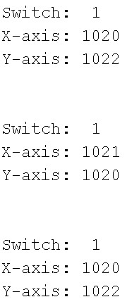
If the joystick was pushed up and to
the far right, for the x and y axis respectfully, the numbers
would display values close to 1023.
Task 2: This
task was roughly the same as the first but instead the signal need to
be transmitted wirelessly to a second Arduino board which would then
print this to the serial monitor. This was accomplished by connecting a
2.4 Ghz transceiver to each Arduino board and using one as a
transmitter and one as a receiver. These modules were very easy to set
up, and within the code they would be defined as a separate serial
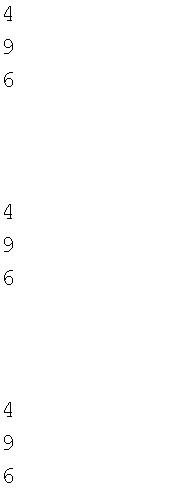
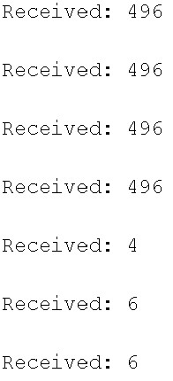
device. (BlueSerial). The first receiver code was designed to print out
one number of the analog joystick at a time.
Each
number was considered to be its own separte value. This was then
changed so the receiver would have its own internal buffer, It would not
print anything till a message end condition was met (\n). This would
tell the Arduino it has finished transmitting one message and can print
the number as a completed line, not broken up as seen above.
Task 3: For
the final task we gave the Arduino that was receiving the information an
additional task, to control the direction of a stepper motor.
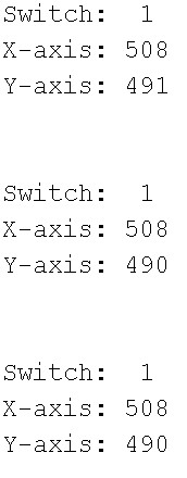
This was done by the use of a simple if statement, if the received value
was a given amount away from the joysticks idle state (around 500) the
motor would turn in a given direction.
Conclusion:
Overall
this project was simple yet made a complicated task easy to understand
and manipulate. We learned how to wirelessly communicate with two Arduino
boards and use that signal as a way to control a stepper motor. ---------------------------------------------------------------------------------------------------- END