CE 351 Fall 2020
The Arduino
KeNeda Randall
1. Introduction
In
this lecture, the fundamentals of the
Arduino C language are introduced. The important contents in this
lecture are
data types, operators, the ‘for’ loop, the ‘while’ loop, the ‘if’
statement,
and the ‘switch’ statement’.
2. The Code and the Results
Part 1.
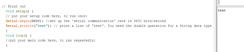
Figure 1: This is an example of creating a setup and loop
function. The setup function initializes and sets the starting values
while the loop function loops through any coomands that control the
arduino through serial communication. Here an initial "test" response
is performed.
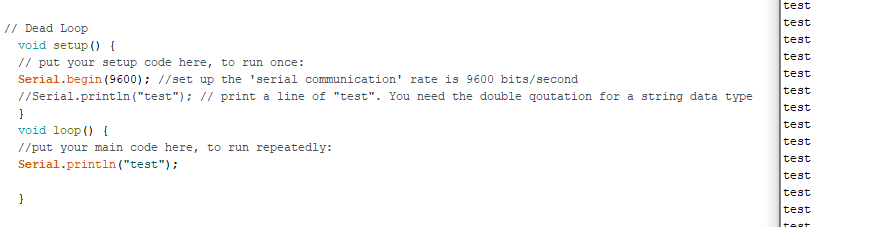
Figure 2: This is deadloop. This shows the loop functions
ability to continuosly loop through a command unless the funciton is
terminated using a 'Serial.end();'. In that case the loop function is
initalized once.
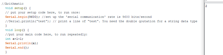
Figure 3: Simple arithmathic is accomplished using serial
communication. 'a' is represented as an integer using the 'int'
(interger) command and the operation is performed by the Arduino chip.
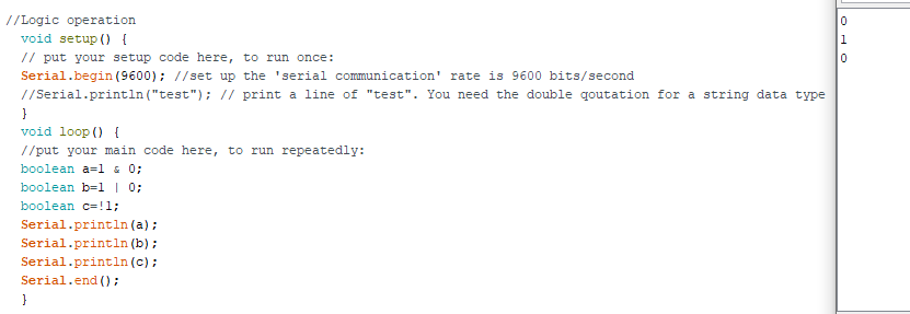
Figure 4: This is logic operation using boolean data type
operators (AND &, OR |, NOT !) . A boolean operator only has two
pssible values, usaully 'true' or 'false'.
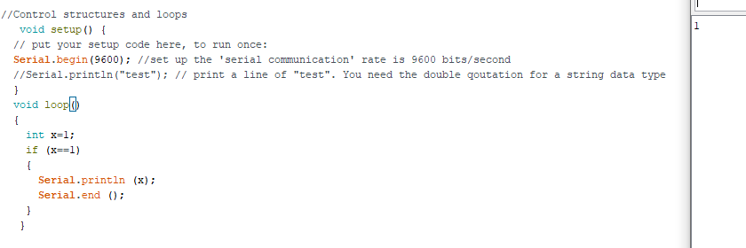
Figure 5: This is an 'If' statement. An 'If' statement
evaluates the function using comparison operators, to check for the
conditions listed, either for a 'true' or 'false'.
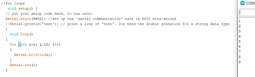
Figure 6: This is a 'For' loop. A 'For' loop repeats a
function until a coniditon is met. It is used in conjunction with
arrays and an increment counter to repeatively loop through statments until a 'false' condition is met.
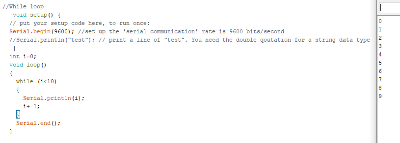
Figure 7: This is a 'While' loop. A 'While' loop inifinitely tests a condition statement until it becomes 'false'.
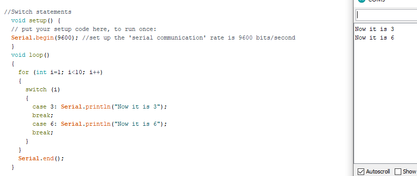
Figure 8: This is a 'Switch-case' Statement. A 'Switch'
statement compares a value to various case statements for a match. When
a match is found the case statement is executed and ends with a 'break'
to keep the case from repeatedly executing.
Part 2.
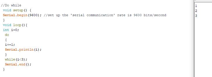
Figure 9: This is a
'Do-while' loop. The 'Do-while' loop is similar to the 'While' loop
except the statement is executed before reaching the condition. The
conditon is returned either as a 'true' or 'false' and the loop
continues or stops.
Part 3.
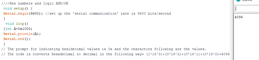
Figure 10: This a Hexidecimal
number (0x1000) returned as a decimal numder (4096). The command '0x'
indicated the value as hexidecimal value and uses the operation [
(1*16^3)+(0*16^2)+(0*16^1)+(0*16^0) ] to convert the value to decimal.
Part 4.
Table 1: Conversion of the binary and decimal numbers to hexidecimal using the operations:
binary to hex: grouping in fours and finding the equivalent hex value; adding 0x to represent a hex value for arduino
dec to hex: (55/16=3.4375), (0.4375*16=7), (3/16=0.1875),(0.1875*16=3);adding 0x to represent a hex value for arduino
1000 1111 0011 0101 (binary)
|
0x8F35
|
55 (decimal)
|
0x37
|
11 (binary)
|
0x3
|
Part 5.
Table 2: Conversion of hexidecimal values to binary representation in Arduino.
HEX
|
Binary
|
0xFFFF
|
B1111 1111 1111 1111
|
0x3210
|
B0011 0010 0001 0000
|
0xABCD
|
B1010 1011 1100 1101
|
Part 6.
The following figures show
the code for using a bitmask to display a 5-bit binary number using
LEDs wired in parallel. An array is used to gather the information for
each LED and is used to turn off/on the LEDs after looping through the
'for' and 'if' statements.

Figure 11: Command or executing '2'

Figure 12: The resulting display
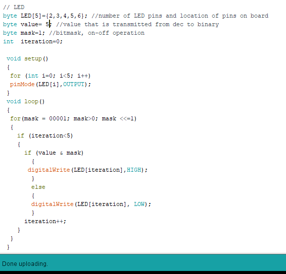
Figure 13: Command or executing '5'
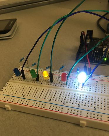
Figure 14: The resulting display

Figure 15: Command or executing '9'
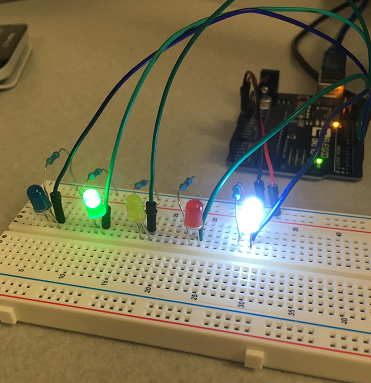
Figure 16: The resulting display
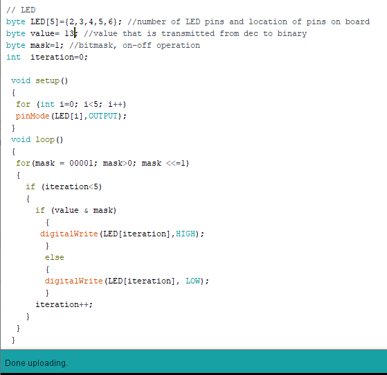
Figure 17: Command or executing '13'
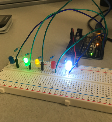
Figure 18: The resulting display
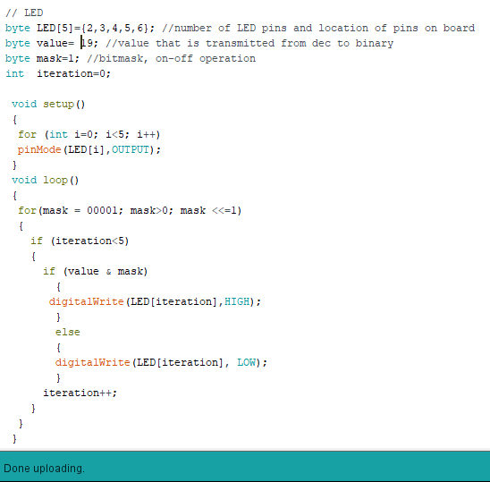
Figure 19: Command or executing '19'
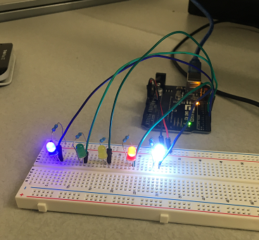
Figure 20: The resulting display
..........................