CE433 2022 Spring
Week 2
John Hitti
jdhitti@fortlewis.edu
Week 2
Introduction
In this week's project we will be reviewing binary number systems and
operations as well as exploring some of the datatypes used in Verilog
for programming FPGAs. We will also be creating programs that use
combinational logic to perform simple tasks on the FPGA.
Task 1
a: What are the fixed point representations of the following decimal numbers?
20.25 in UQ16.16
0000 0000 0001 0100. 0100 0000 0000 0000
0014.4000 (UQ16.16) 128.5 in UQ16.16
0000 0000 1000 0000. 1000 0000 0000 0000
0080.8000 (UQ16.16) 0.125 in UQ.16
.0010 0000 0000 0000
2000 (UQ.16) -38.125 in UQ15.16
1000 0000 0010 0110. 0010 0000 0000 0000 8026.2000 (UQ15.16) -50.0625 in UQ15.16
1000 0000 0011 0010. 0001 0000 0000 0000
8032.1000 (UQ15.16) b. What are the floating point representations of the following decimal numbers?
0.141 in half precision/format S = 1
E = -3
F = 1.128 0011 0000 1000 0011 - 3083(16)
3.625 in half precision/format S = 1
E = 1
F = 1.813 0100001101000000 - 4340(16)
-15.25 in half precision/format S = -1
E = 3
F = 1.907
1100 1011 1010 0000 - CBA0 (16)
Task 2 In this task we will show the process of floating point addition/subtraction of the following operations.
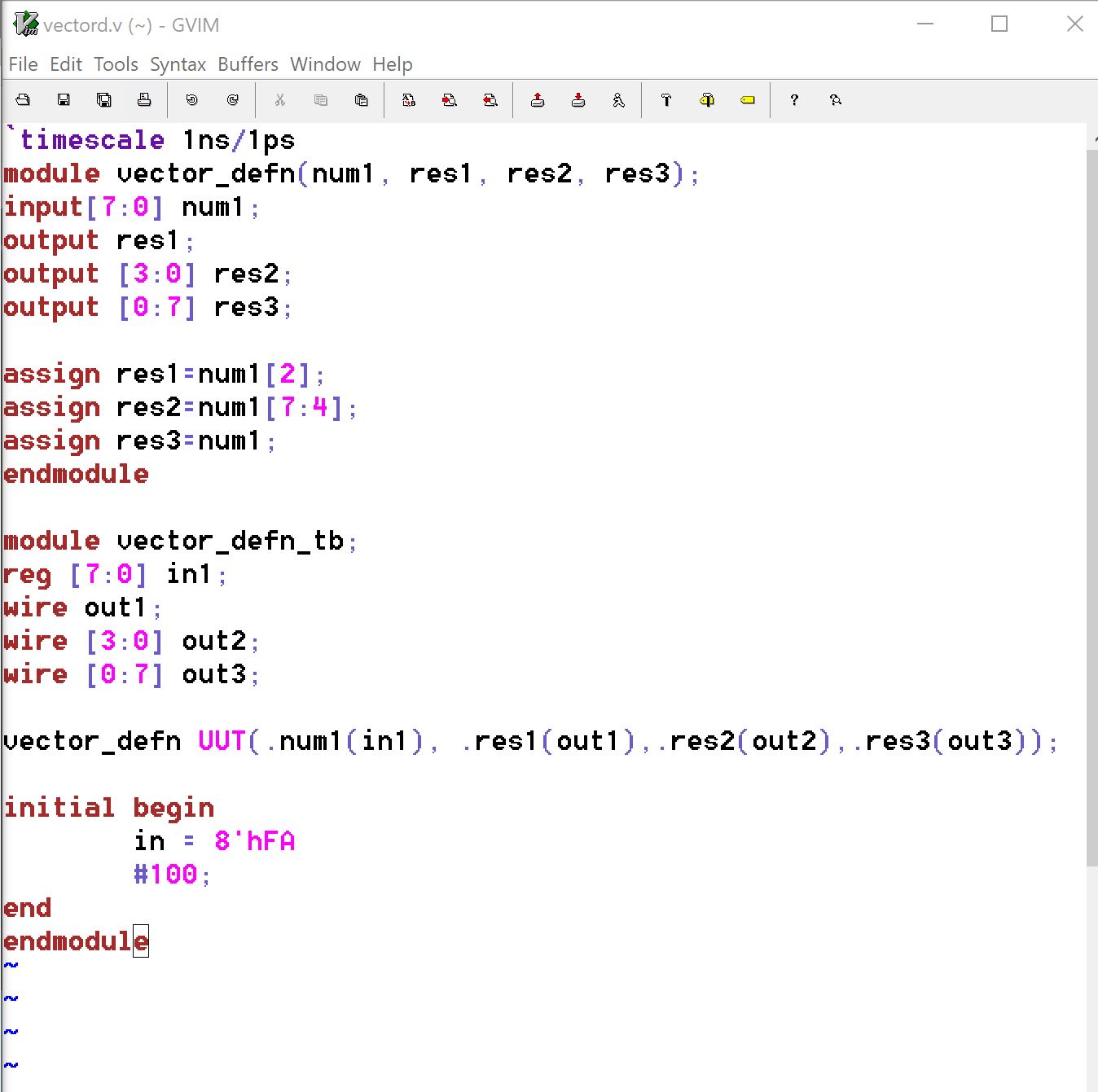
Task 3 In this task we were directed
to repeat the simulation work done on problem 11 involving Nets and
Data Types. We started by coding the simulation example which utilizes
vectors and other various data types. A
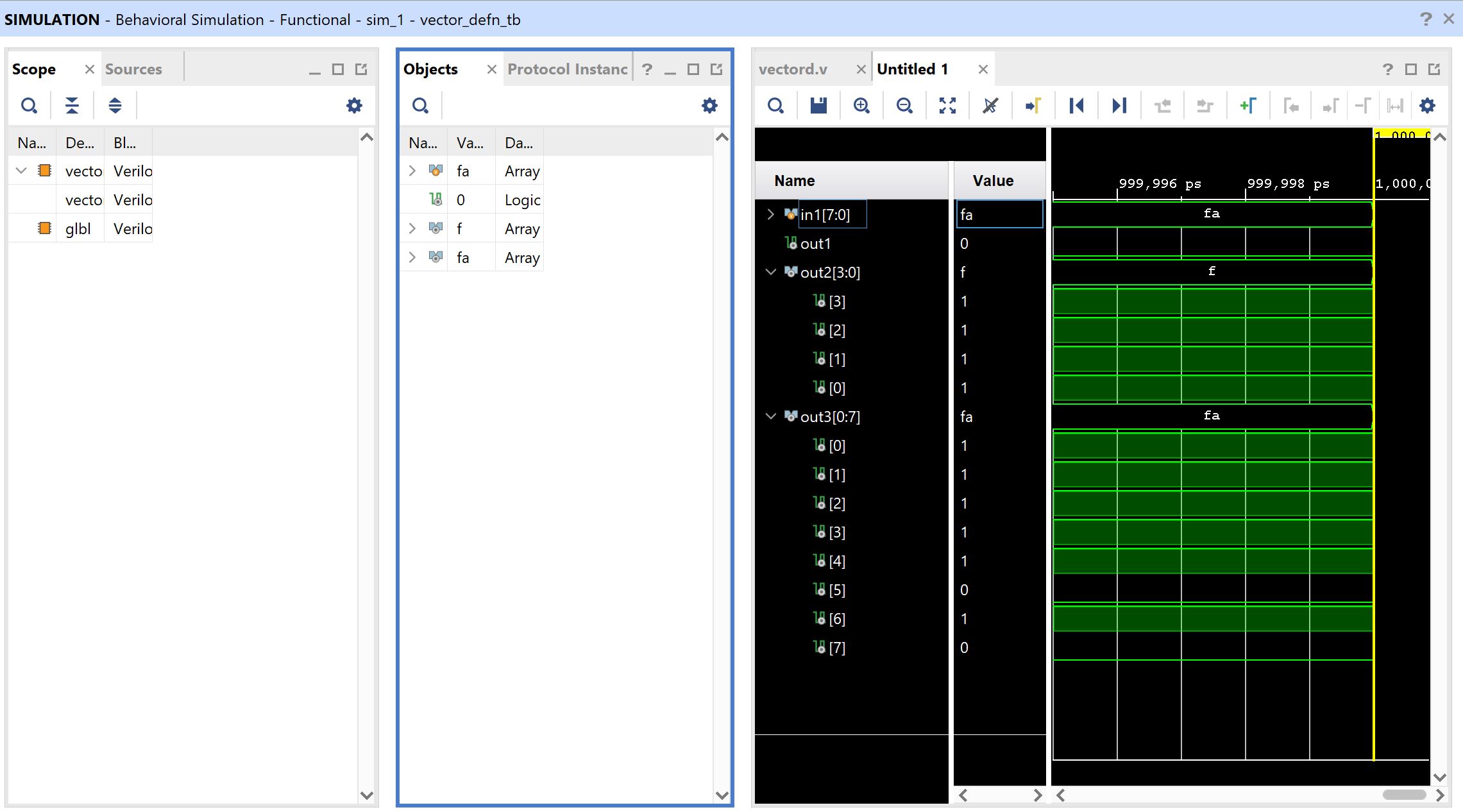
simulation is then ran using the example to demonstrate the
functionality. An vector of data values is sent to the vector_defn
module and it returns vectors and a data value. These values are
observed below.
Task 4 In this task we repeated the
simulation work done in section 14.1, 14.2 and 14.2. This simulation
work involves uploading simple programs to the FPGA board.
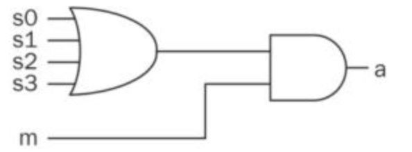
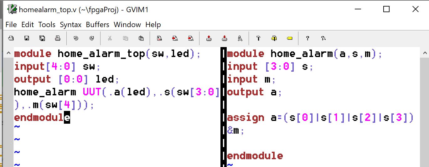
14.1 In this task we are creating
a home alarm system that follows the below diagram. When "m" is enabled
any of the four sensors can activate the alarm.
This is then coded into Verilog with the appropriate testbench to upload the program to the FPGA.
The code can then be uploaded to the FPGA to verify functionality.
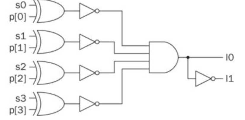
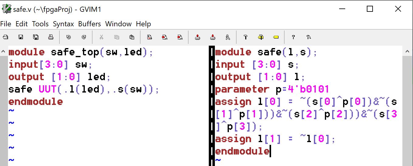
14.2 In this task we are creating a digital safe system using the below diagram.
This is then coded into Verilog with the appropriate testbench to upload the program to the FPGA.
The code can then be uploaded to the FPGA to verify functionality.
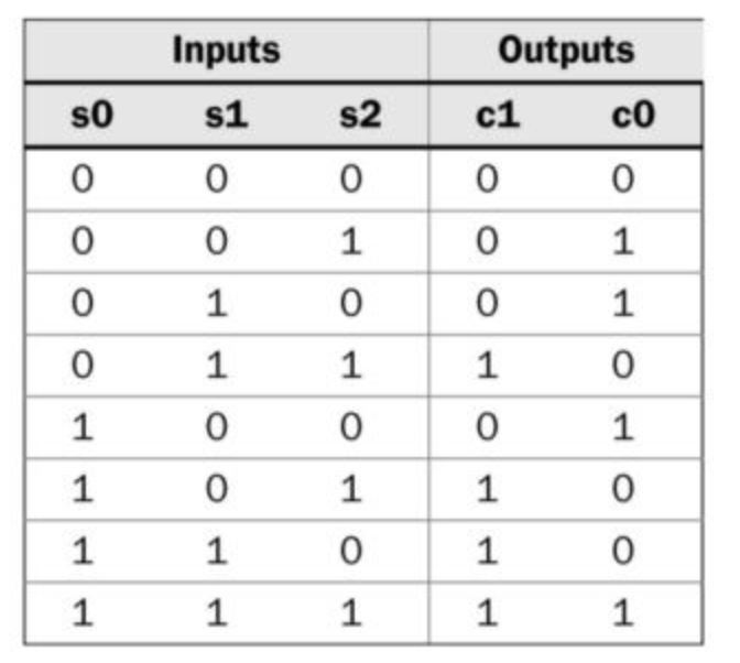
14.3 In this task we are creating
a counting system to check the amount of remaining parking spots for a
set of three parking spots. This task will follow the truth table below
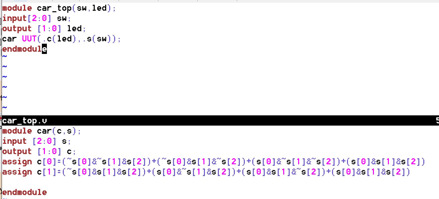
to display the remaining spots available.
This is then coded into Verilog with the appropriate testbench to upload the program to the FPGA. The code can then be uploaded to the FPGA to verify functionality.
Discussion This
project is an excellent introduction to using the FPGA for more
complicated programs using combinational logic as well as introducing
us to some of the many different data types we can use in
Verilog. This will be very helpful as we explore more Verilog and
FPGA applications.