CE432 2020 Fall
Tutorial 1
John Hitti
jdhitti@fortlewis.edu
Tutorial 1 - Getting Started
Introduction
In this tutorial we will be setting up the ESP32-CAM board to stream a
video feed to a device via WiFi connection. The board features a camera
in conjunction with the popular and feature rich ESP32 MCU with
integrated WiFi and Bluetooth. This board also features a bright LED
that can be used as a flash for a camera or for general illumination.
This board also features several GPIO pins. Once we have set up the
ESP32 to stream video data we will then test out some of its other
features.
Task 1. The first example We start our
first example by loading an example code onto the ESP32. The function
of this code is to stream the camera data to our device via WiFi. This example code
is provided alongside the textbook "ESP32-CAM Projects" by Rui Santos
and Sara Santos. In this code we type in the SSID and password of the
WiFi network we want to connect too. Then we can send our code to the
board.
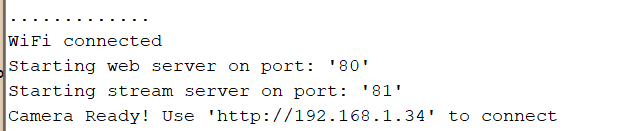
Figure 1. The serial output from the ESP32 which contains the IP address to access the stream
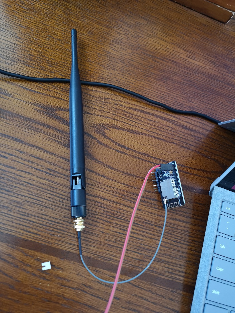
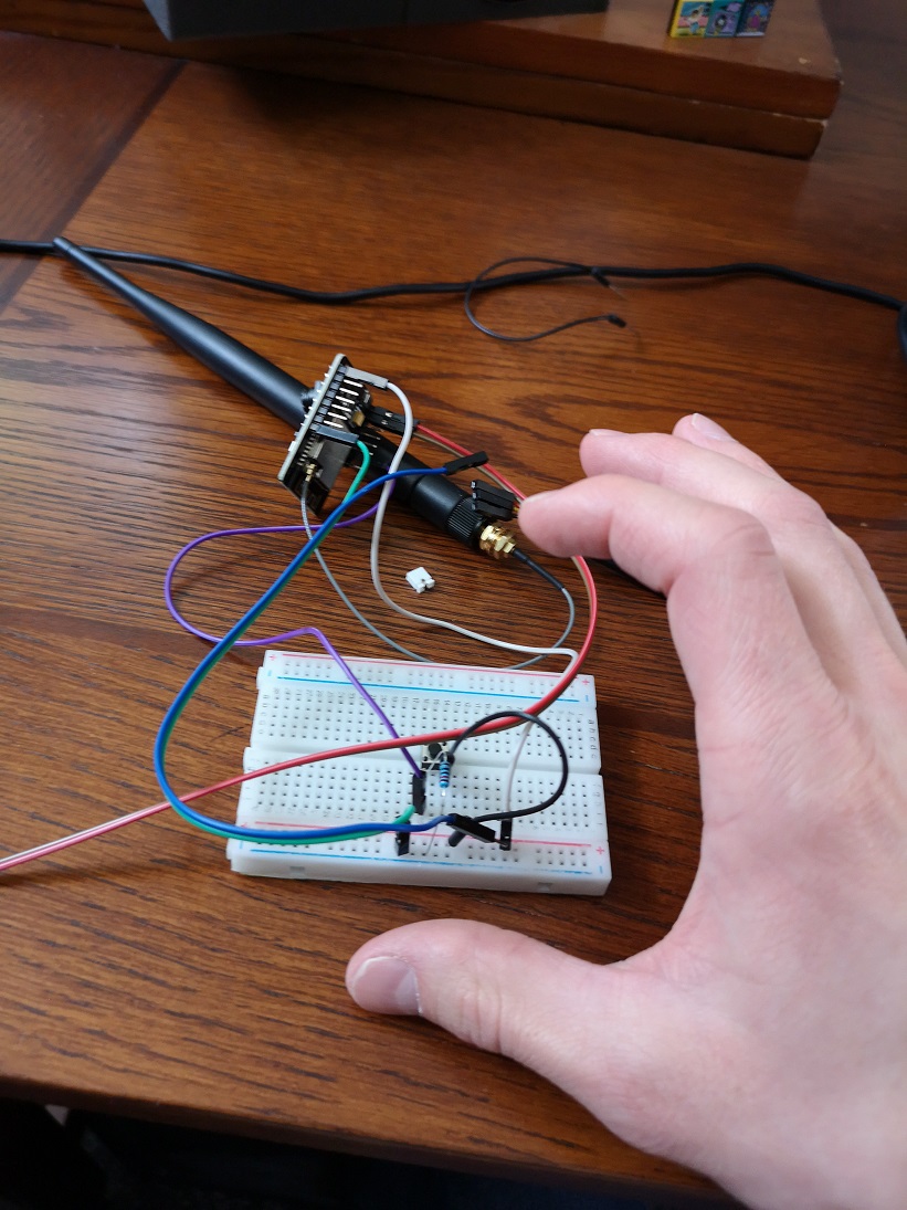
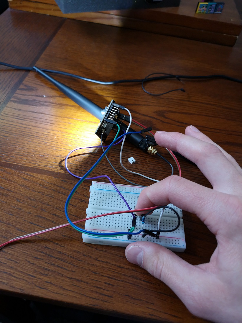
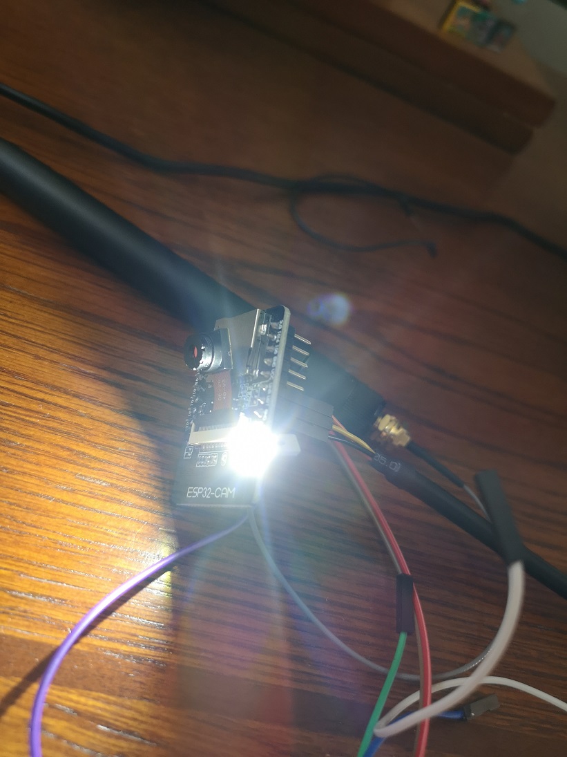
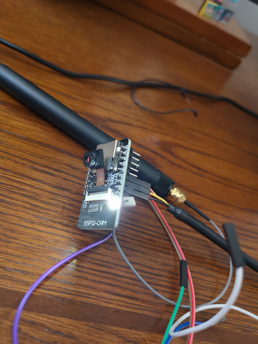
To properly stream the video a larger antenna must be connected to the ESP32 to increase the bandwidth.
Figure 2. The large antenna is attached to the ESP32.
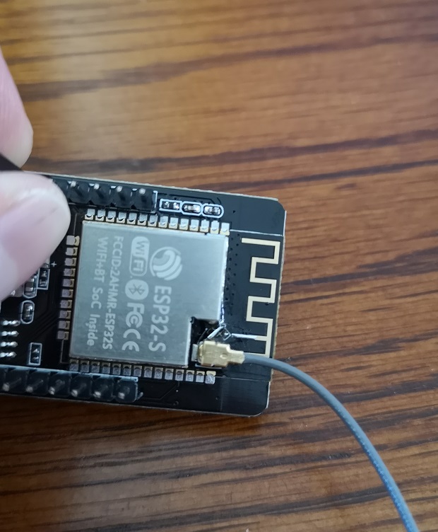
Figure 3. The resistor bridging the ESP32 and the small antenna must be switched to bridge the ESP32 and the antenna socket.
A resistor on the ESP32 board
must me moved over to enable the large antenna. Since this is a
zero-ohm resistor it was replaced with a small piece of wire.
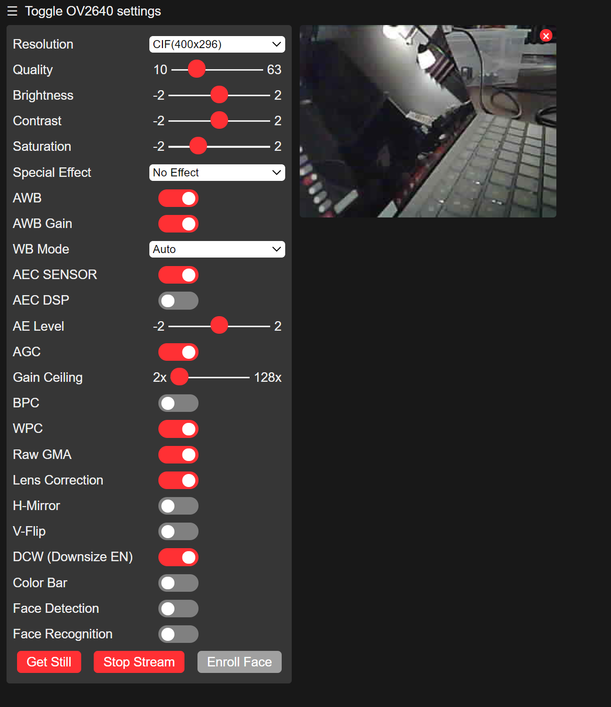
Once the code is uploaded and we open up the IP address on a browser, we are presented with a GUI and the camera stream.
Figure 4. The GUI and camera stream from the ESP32.
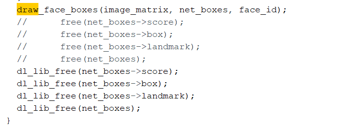
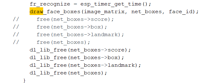
The code provided also
features facial recognition capabilities. In order for these to
function smoothly, some code must be edited. In the provided app_httpd
file there are two functions where the function call "free()" must be
changed with "dl_lib_free()". Changing these function calls will
prevent the ESP32 from rebooting when the face detection setting is
toggled.
Figure 5. First function where code is edited Figure 6. Second function where code is edited
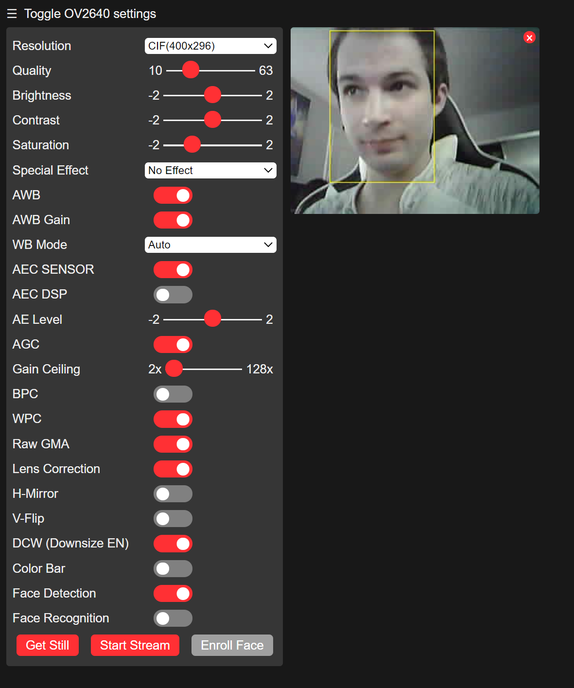
Once the code had been
changed, we can toggle on the facial detection switch. As you can see
the ESP32 has placed a box over my face.
Figure 7. The ESP32 uses facial detection to place a box over my face.
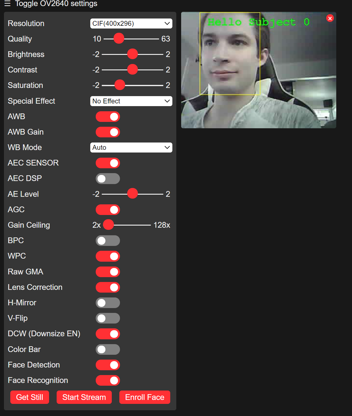
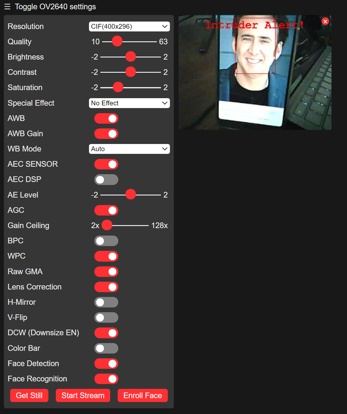
We can also toggle the facial recognition switch and the ESP32 will be able to detect individual faces.
Figure 8. The ESP32 has detected my face as an enrolled face Figure 9. Presenting a new face to the ESP32 will cause it to identify an intruder
Task 2 - Control the flashlight and GPIO pins The ESP32 also
features a bright LED that can be used for a flashlight as well as many
GPIO pins. In this task we will run some examples to test the operation
of the LED and the GPIO pins.
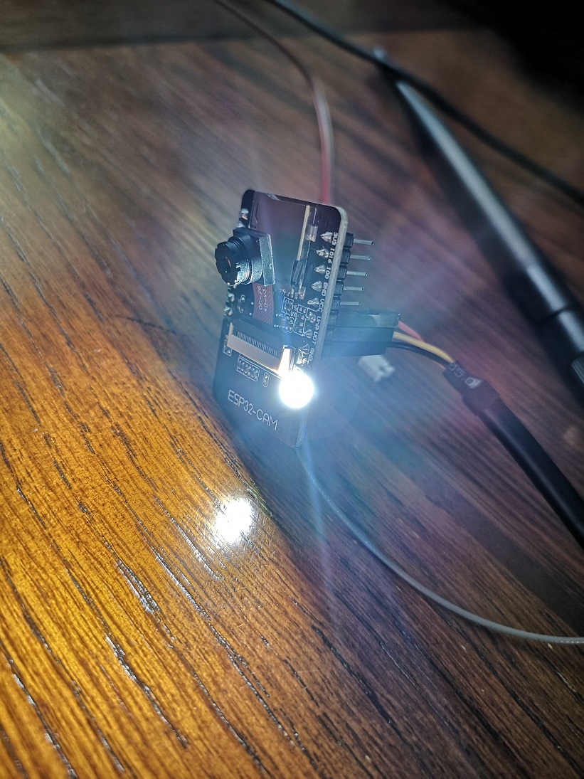
We start by uploading an example code to cause the flashlight to blink on and off every 2 seconds. The flashlight is connected to GPIO4.
Figure 9. The Flashlight during the ON cycle
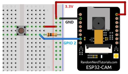
Since the LED is working
properly, we can use a GPIO pin to control the led. A small pushbutton
with a resistor is connected to GPIO pin 2 and when the button is
pressed the LED will light up. The code for this example can be acessed here.
Figure 10. A schematic for the pushbutton provided by the "ESP32-CAM Projects" textbook. Figure 11. The LED is off when the button is not pressed Figure 12. The LED is on when the button is pressed
The brightness of the LED can be changed via PMW. Using the example code provided we can use PWM to fade the LED from off to on.
Figure 13. The LED is at full power. Figure 14. The LED is at half power.
Discussion The
ESP32 CAM is a very feature rich microcontroller board with lots of
potential. The WiFi and Bluetooth conectivity allow for a wide variety
of wireless connectivity and the camera and LED offer an excellent way
to view and process visual data. This board could be used in a wide
variety of applications due to its functionality.