CE 433 Spring 2022
Homework 5
Name: David Lee
Email:
djlee1@fortlewis.edu
Data
Storage
Introduction:
In
this homework assignment we use vivado and verilog to create sequential Circuits
Materials and Methods:
vim, Vivado
Results:
Task 1: From the state table, find the logic equations for q1(n+1) and y and draw the sequential circuit for q1(n+1) and y.
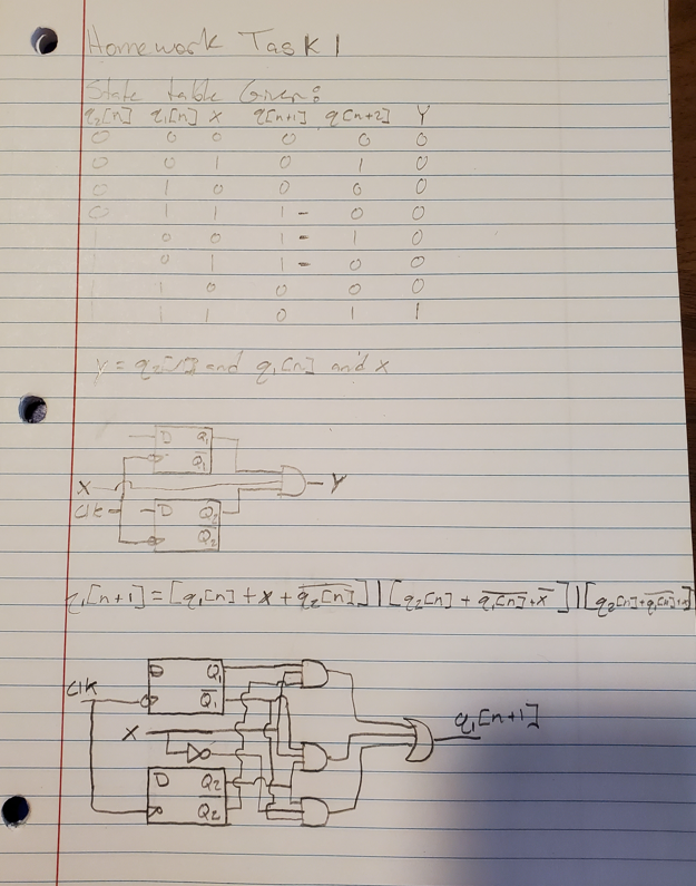
Figure 1: Shows worked out solution
Task 2: Repeat the work in Section 3. Use two methods, the given one and the behavioral one. Show simulation results
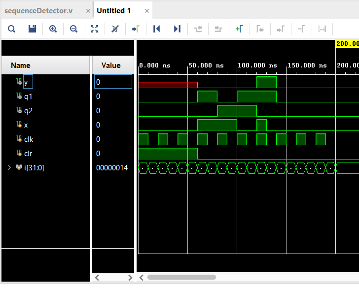
Figure 2: Shows The simulation results of
the SequenceDetector using the first method
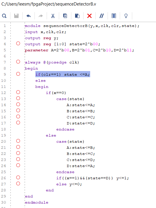
Figure 3: Shows The Code for the SequenceDetector using the first method
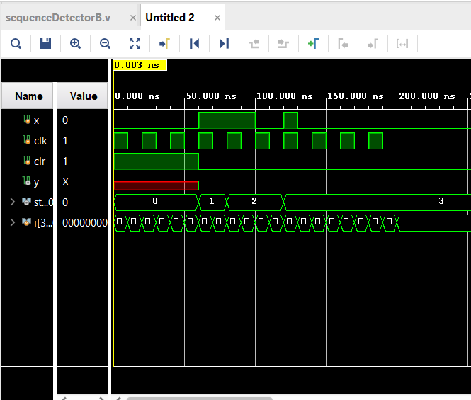
Figure 4: Shows The Simulation of
the Sequence Detector Using Behavioral Method
Figure
5: Shows the Code of the Sequence Detector Using Behavioral Method Top
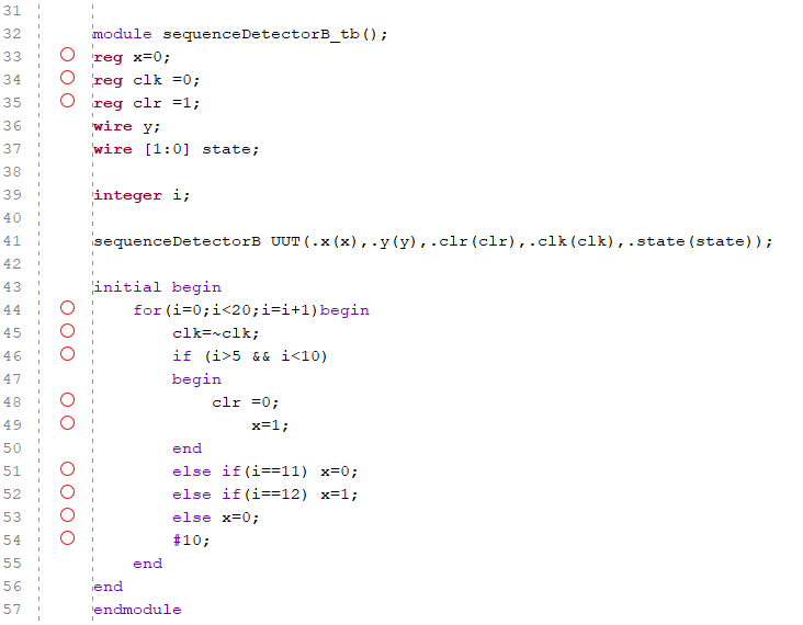
Figure
6: Shows the Code of the Sequence Detector Using Behavioral Method Test Bench
Task 3: Simulate the four types of shift registers in Section 5.
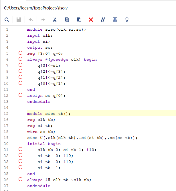
Figure 7: Shows the Code of the
SISO
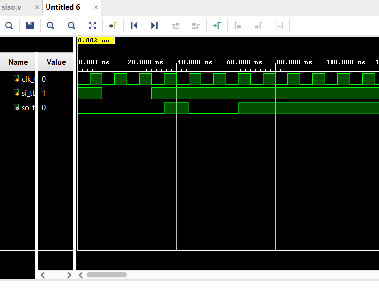
Figure 8: Shows the Simulation of
the SISO
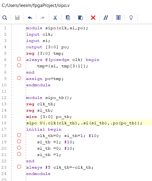
Figure 9: Shows
the Code of the SIPO
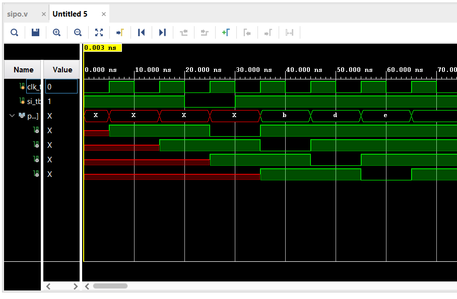
Figure 10: Shows the
Simulation Results of the SIPO
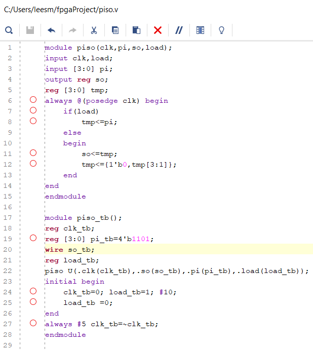
Figure 11: Shows
the code for the PISO
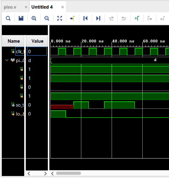
Figure 12: Shows the Simulation of
the PISO
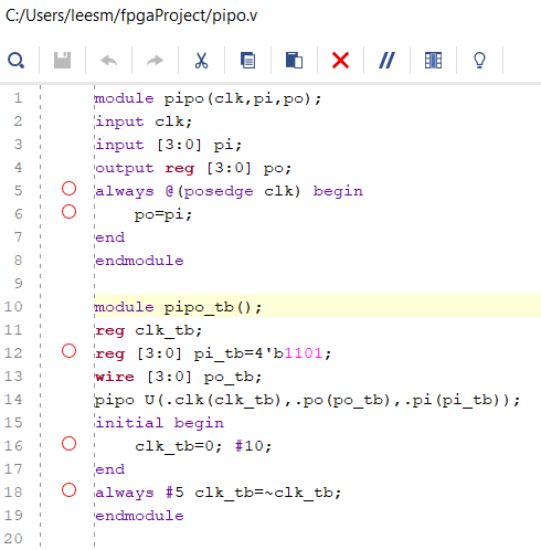
Figure 13: Shows
the Code for PIPO
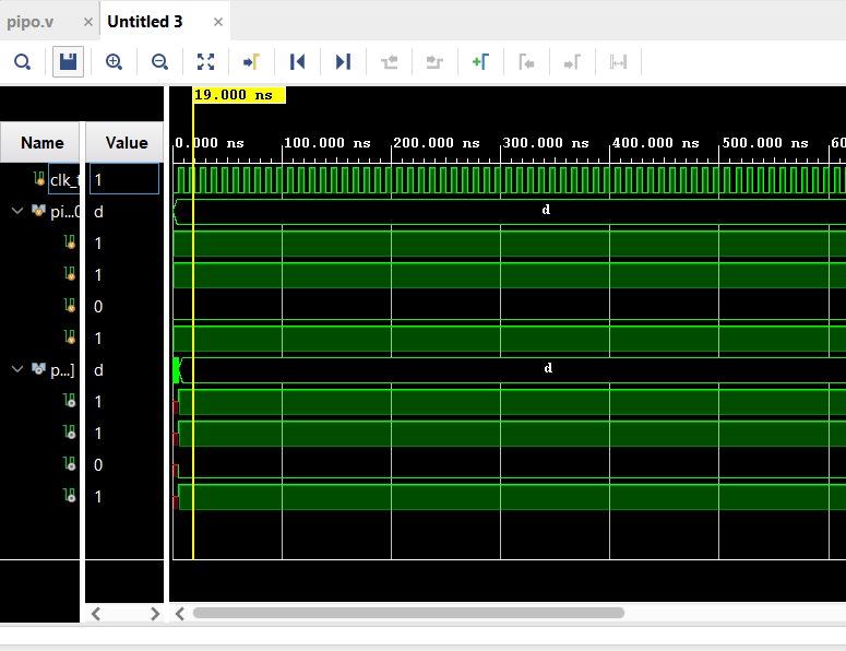
Figure 14: Shows the
Simulation PIPO
Task 4: Build a counter module and show the simulation results.
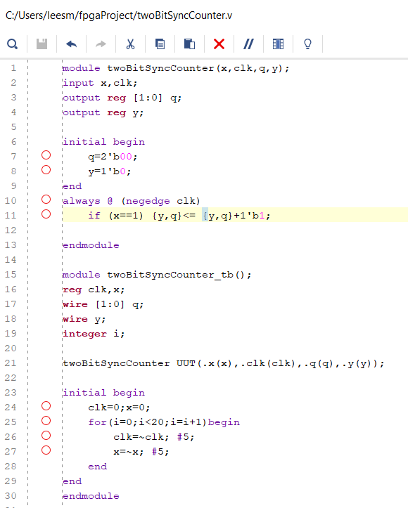
Figure 15: Shows
the Code of the 2-Bit Synchronouc Counter
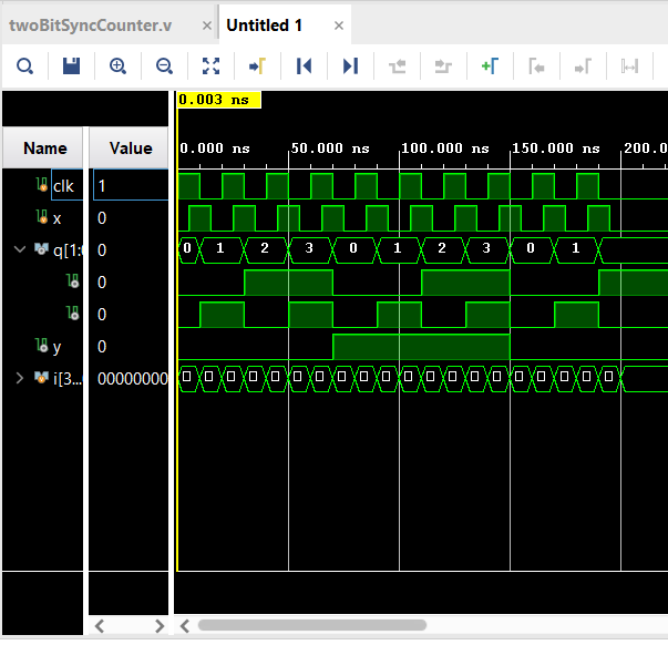
Figure 16: Shows the Simulation of
the 2-Bit Synchronousn Counter
Task 5: Find the logic equation of the following circuit and implement it in verilog. Show the simulation results.
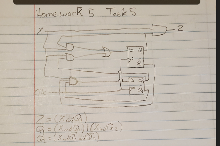
Figure 17: Shows
the HandWritten work of the Circuit Given
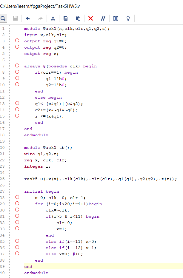
Figure 18: Shows
the Code of the Circuit Given
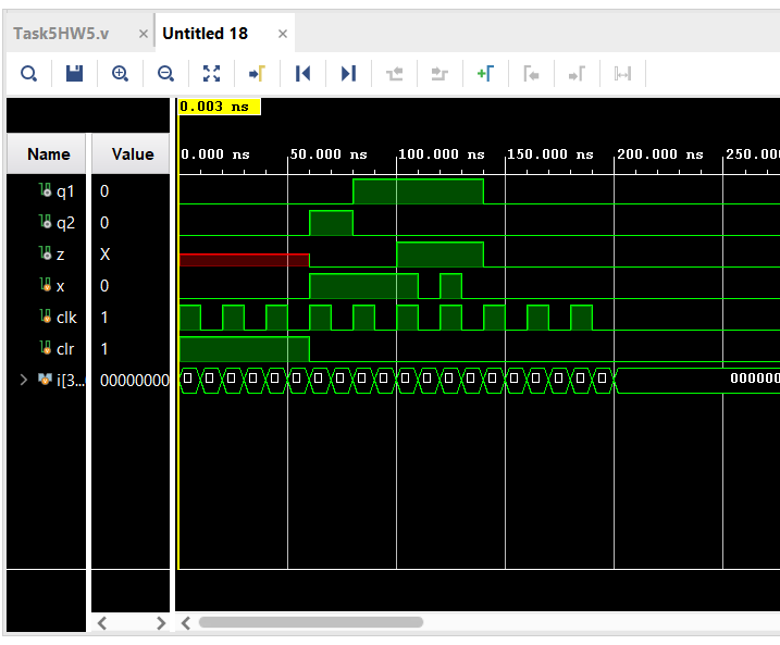
Figure 19: Shows
the Simulation of the Circuit Given
Discussion:
This
assignment was able to be successfully completed. The only parts I
struggled on a bit was creating the logic equations for the circuit in
Task 5 and the Logic equations in Task 1 because it has been a while
since I have done those. However it was a good thing to practice and
complete getting a circuit from a schematic and having to create a
simulation of it in Vivado.