CE 433 Spring 2022
Homework 3
Name: David Lee Email:
djlee1@fortlewis.edu
Combinational
Blocks
Introduction:
In
this homework assignment we use create simulations to see the functions
of many different combinational blocks.
Materials and Methods:
vim, Vivado and a FPGA board
Results:
Task 1: Repeat the simulation of Half Adder and Full Adder in
Section 1
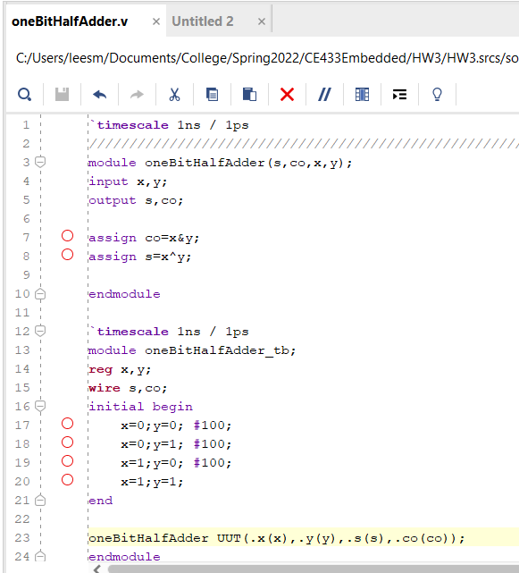
Figure 1: Shows The code
for the Half Adder
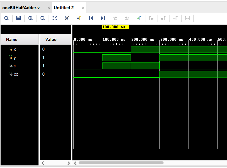
Figure 2: Shows The simulation results of
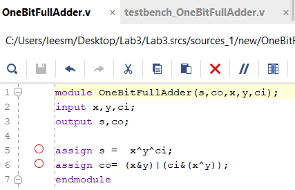
the Half Adder Figure 3: Shows The Code for the
Full Adder
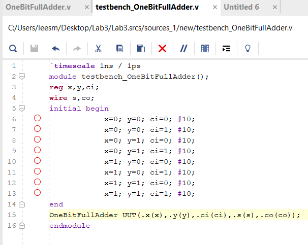
Figure 4: Shows The code used to
run the simulation of the Full Adder
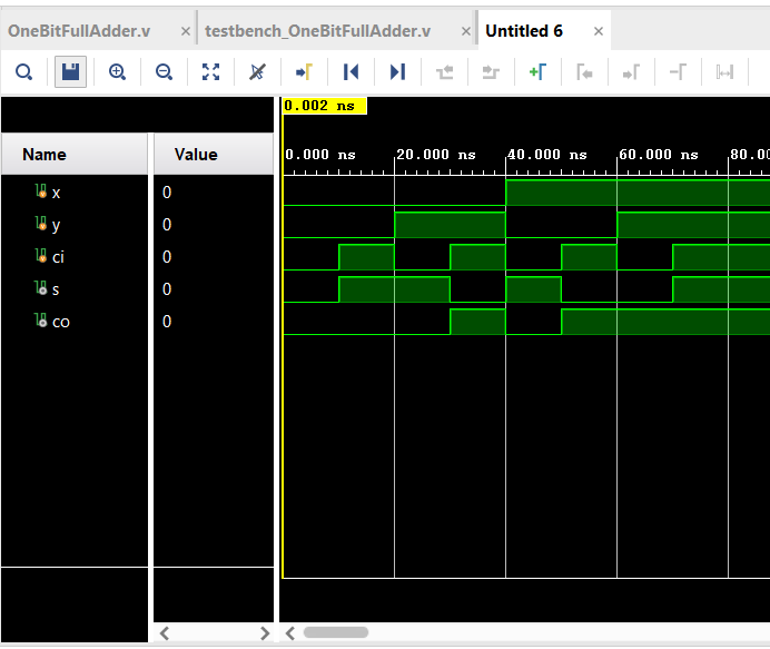
Figure
5: Shows the simulation results in vivado of the Full Adder
Task 2: Design the Test
Bench for the comparator in section 2 and show the simulation results
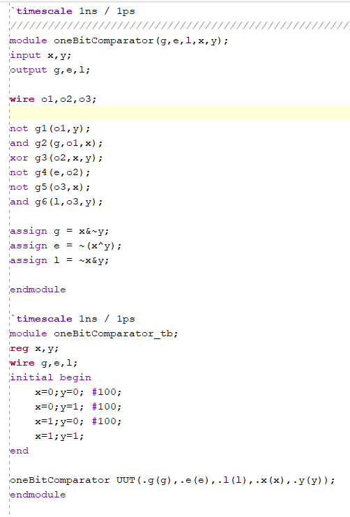
Figure 6: Shows the
gvim code for the comparator
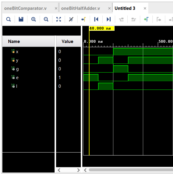
Figure 7: Shows the simulation
results of the Comparator
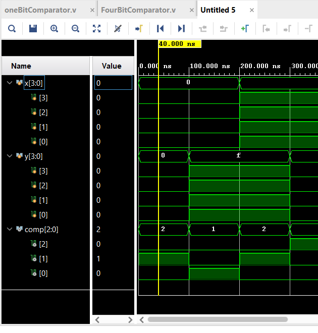
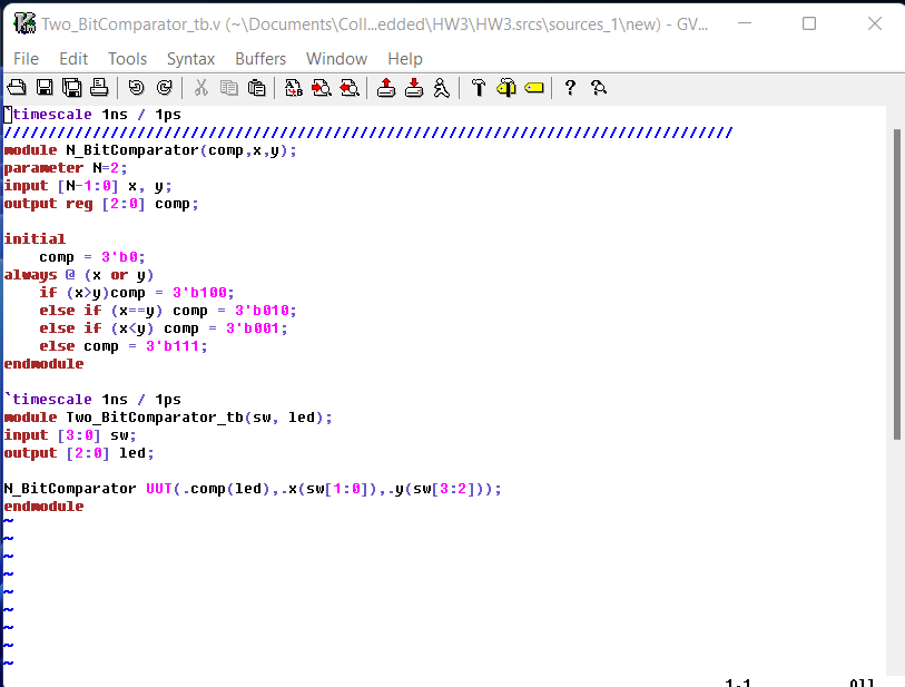
Task 3:
Design the Test Bench for the 4-bit comparator in section 3 and show
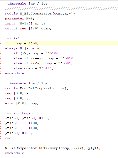
the simulation results Figure 8: Shows the code for the
4-bit Comparator
Figure 9: Shows
the Simulation results of the 4-bit Comparator Task 4: Implement a 2-bit
comparator on the Basys 3 board.
Figure 10: Shows the
Code for the 2-bit Comparator Used on the Basys 3
Figure 11: Shows
the Results of the Vivado work on the board of example 14.3
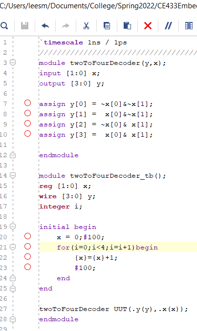
Task 5: Design the Test
Bench for the decoder and verify the logic in simulation
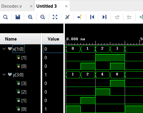
Figure 12: Shows the
Code for the 2-4 Decoder Figure 13: Shows
the Simulation results of the Decoder
Task 6: For the 8x3
priority encoder, Find Q1 and Q2, Build the module and verify the logic
using simulations
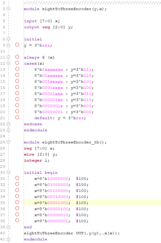
Figure 14: Shows the
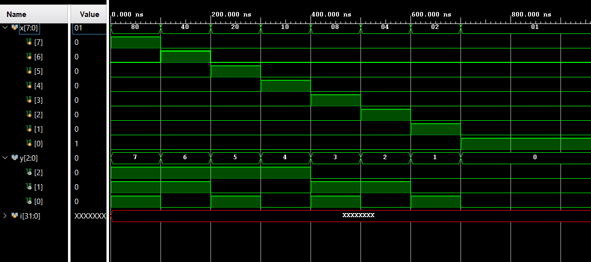
Code for the 8x3 Encoder Figure 15: Shows
the Simulation Results of the 8x3 Encoder
Task 7: Implement
a 4-1 multiplexer on your Basys 3 Board.
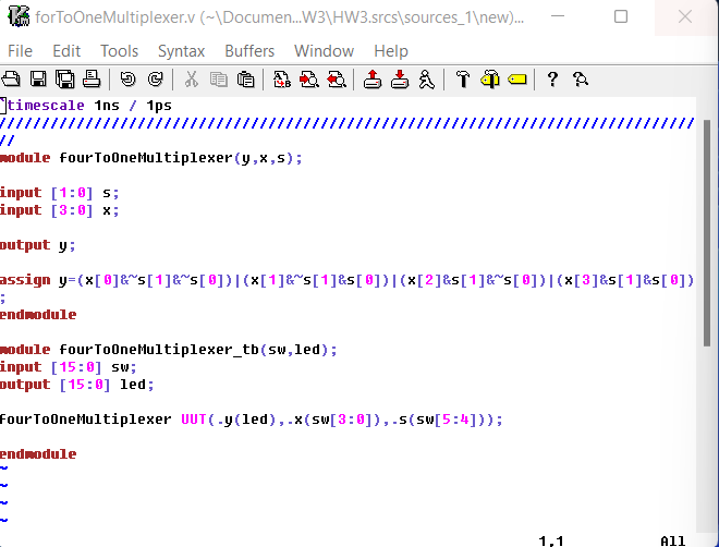
Figure 16: Shows the
Code for the 4-1 Multiplexer
Figure 17: Shows
the Video of the Multiplexer in use
Task 8:
Design/Verify an even parity generator and checker in simulation.
Implement it on the Basys 3 Board.
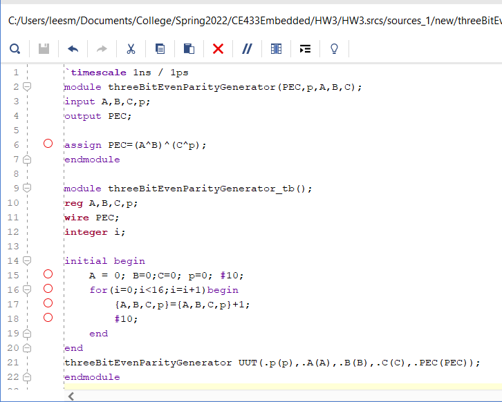
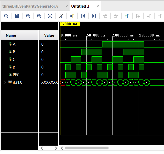
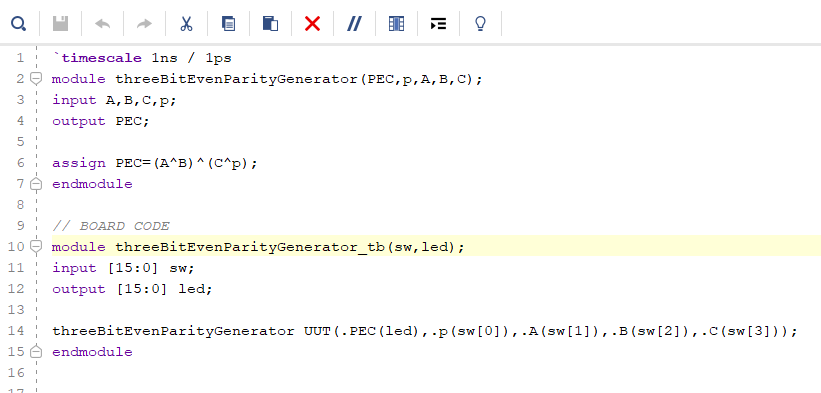
Figure 18: Shows the
Code for the Even Parity Generator and Checker for Running Simulations Figure 19: Shows
the Simulation Results
Figure 20: Shows
code for Running the Parity Generator and Checker on the Basys 3
Figure 20: Shows
the Even Parity Generator and Checker in use on the Basys 3 Board
Task 9: Implement
the design in section 8 and section 9 on your Basys 3 Board.
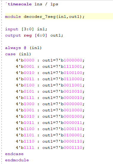
Figure 21: Shows the
Code the helped the Digital Display on the Basys 3 Board to Function Figure 22: Shows
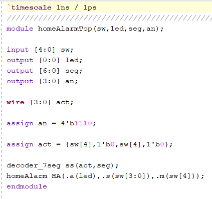
the Code for the Home Alarm System(Section 8)
Figure 23: Shows
the Home Alarm System in Use
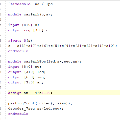
Figure 22: Shows
the Code for the Car Counter System(Section 9)
Figure 23: Shows
the Car Counter System in use
Discussion: This
assignment was difficult at for me at first because I was still not
very Familiar with the formatting of the verilog inorder to correctly
run the simulations and board. But after trying many times I was able
to be understand the formatting and successfully complete the Tasks
with only minor errors the first go. This Homework assignment was
really fun to do because I was able to get a better understanding of
the verilog and functions of the Basys 3 Board.