CE 351 Spring 2022
Homework 5
Name: David Lee Email:
djlee1@fortlewis.edu
PID
Control - Photocell
Introduction:
In this homework assignment we learn about PID and how it can control
the rate at which something will self correct.
Materials and Methods:
Using Python, Arduino and a bread board we follow the instruments to
make reading on the photocell do what we want
Results:
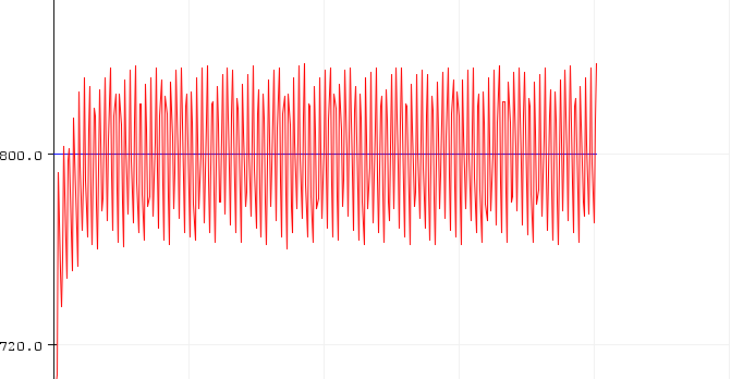
Task 1: Make the light
being sensed oscillate around a set point
Figure 1: Shows
the light ocsiallting around 800
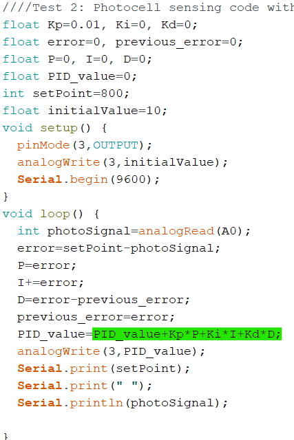
Figure 2: Shows the code fixed to
make it work
Task
2: Save the data and us Python to plot
the results from the Sensor using an extra LEd to create extra ambeint light which will make the Main led dim
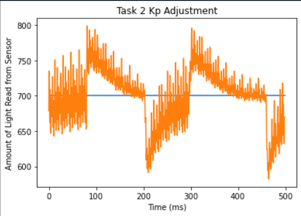
Figure 3: Shows the Python Graph
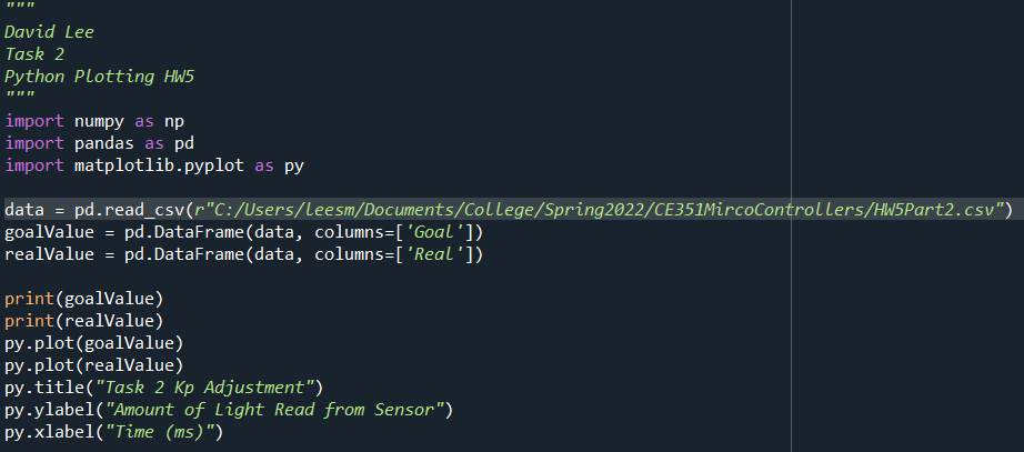
Figure 4: Shows the python Code.
Figure
5: Shows the code Used for the Task
This Task used the same code as task 1. However. There was an
additional LED connected by a button that would turn on and make the
LED connected to pin 3 adjust and go dimmer. That is why we are able to
see the self correction the graph produces in Figure 3.
Figure 6: Shows a Video of the Kp set to .001.
The figure above demonstrates how the Kp affect the correction time. The Kp in Figure 3 was Kp=.01 and was able to correct relatively fast. At Kp=0.001 We see almost no correction in a short period of time
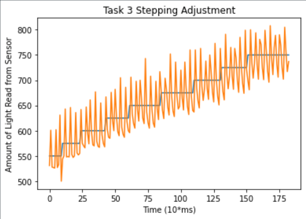
Task 3: Save the data and us Python to plot
the results from the Sensor which steps the set value and makes the LED adjust to the new Setpoint.
Figure 7: Shows the Python Plot of the Data
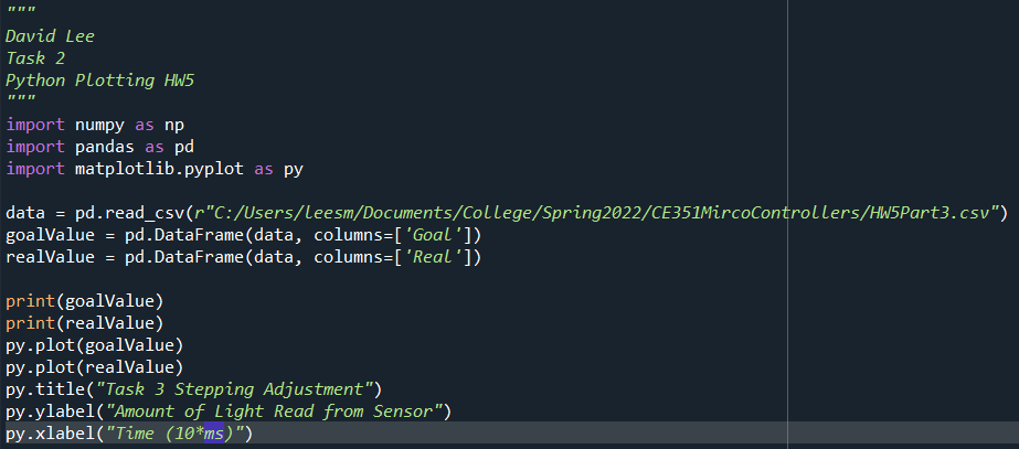
Figure 8: Shows the Python code
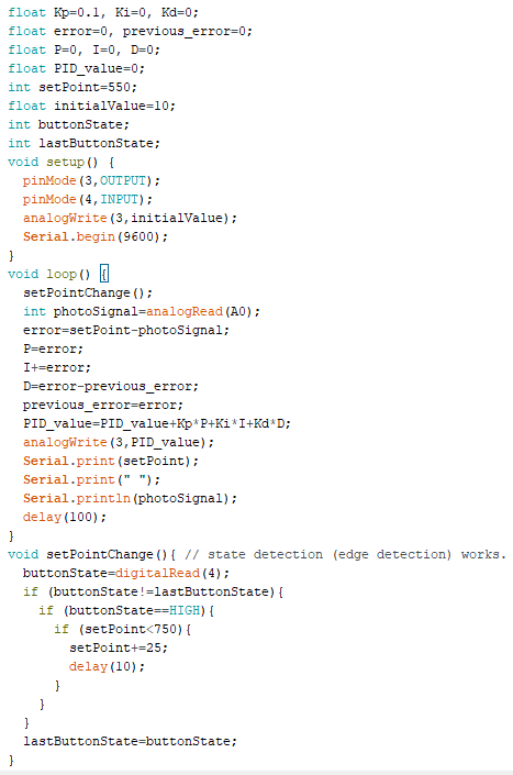
Figure 9: Shows the Arduino code used for the funciton
Discussion: This
assignment was good to complete. It introduced me to exporting data and
made me review my python coding practices. I was able to successfully
complete the assignment.