Introduction This lab
is to understand the control of the VGA output using the Basys 3 FPGA.
Rather than simply changing the entire screen color or image, we may
attempt to control each pixel.
Materials and Methods
Basys 3 Board
Vivado
gVim
VGA Cable
Monitor (VGA Compatible)
Procedure We may use the implementation from HW6
for the VGA pixel control. The following screenshots show the changes
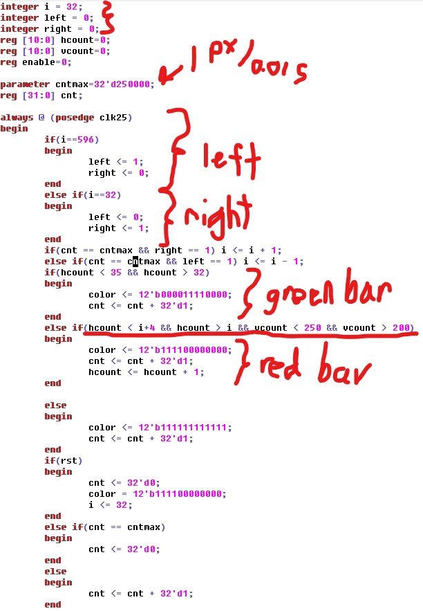
made to the original code. Figure 1 shows drawing of the green line of
width four from pixel 32 to 35, the drawing of the red bar with
boundaries x = [600,605] and y = [200,250], and how the bar is moved
across the screen.
Figure 1. Verilog code for the VGA pixel control.
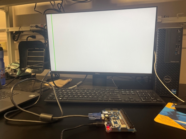
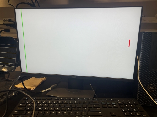
Results Figures 2 and 3 show the green line and the red bar respectively.
Figure 2. Green line displayed with VGA.
Figure 3. Green line and red bar displayed with VGA.
Here
are videos of the red bar moving left to right 0.5 pixels per second
and bouncing at a rate of 0.01 pixels per second, respectively.
Discussion This
lab showed to be quite interesting when trying to figure out which
parameters to change to create the necessary motion. When working at
this level (Verilog), you are able to see the "behind the scenes" and
work using every pixel. A lot was learned during this lab.