ENGR338 Lab Spring 2021
Lab 9: Design a Simple 8-bit ALU in ElectricVLSI
Name: Audra Benally
Email: albenally1@fortlewis.edu
1. Title: Design a Simple 8-bit ALU in ElectricVLSI
2. Introduction: In this lab we combined the previous 8bit
components to make a simple 8 bit ALU. The ALU was created in schematic
and layout cells and has been tested in several simulations.
3. Materials and Methods:
Materials:
- Computer
- Computer Mouse
- LTSpice Software
- ElectricVLSI Software
Methods:
For this lab,
we created a simple
8bit ALU. Most of the components were already created in past labs so
the only one I had to make for this lab was the 8bit inverter. After I
had finished I started making the layout since I knew this would take
the longest time. I drew a rough idea of how I wanted to layout the
schematic then I got to work. The layout was tricky but I was able to
get it to pass DRC, NCC, and well checks. Once the ALU was finished it
was tested in various simulations shown in the figures 4-7.
4. Results:
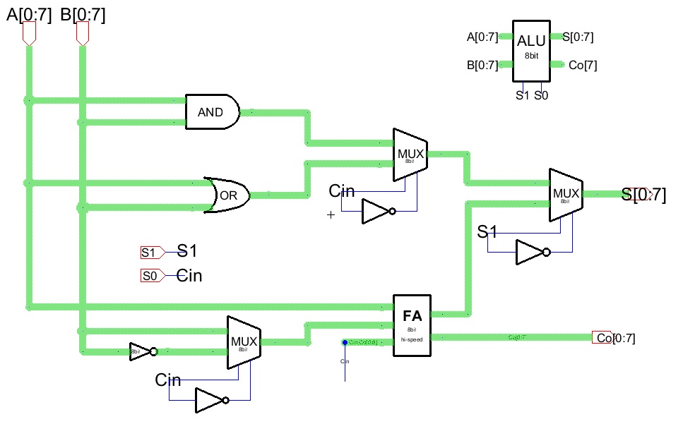
Figure 1.
8bit ALU schematic made from the 8bit components made this semester.
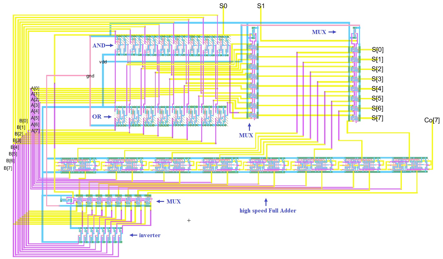
Figure 2.
8bit ALU layout. A[0:7] and B[0:7] inputs are on the left. S0 and S1
pins are on the top. S[0:7] and Co[7] outputs are on the right.
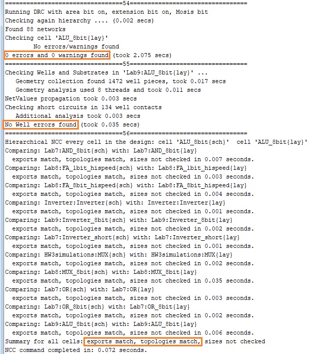
Figure 3. DRC, NCC and well checks for the ALU.
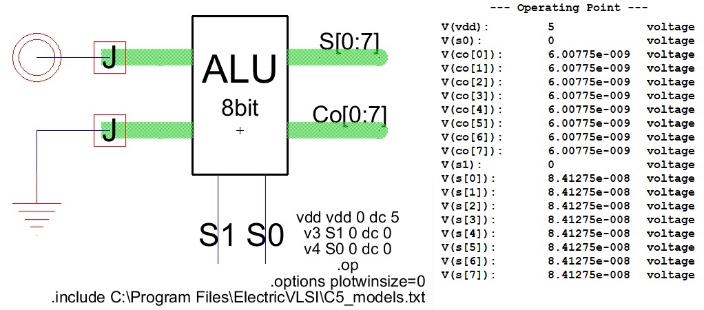
Figure 4. S0=0 & S1=0: AND logic simulation.
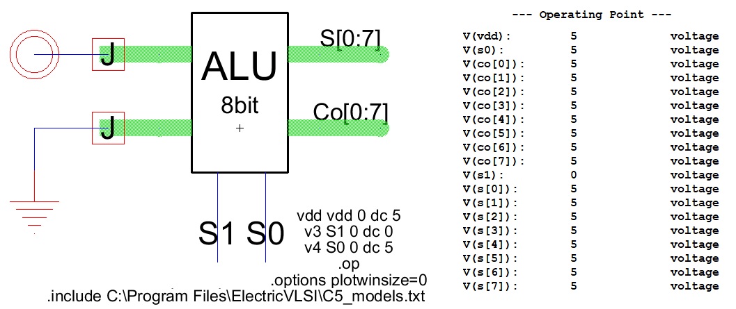
Figure 5. S0=1 & S1=0: OR logic simulation.
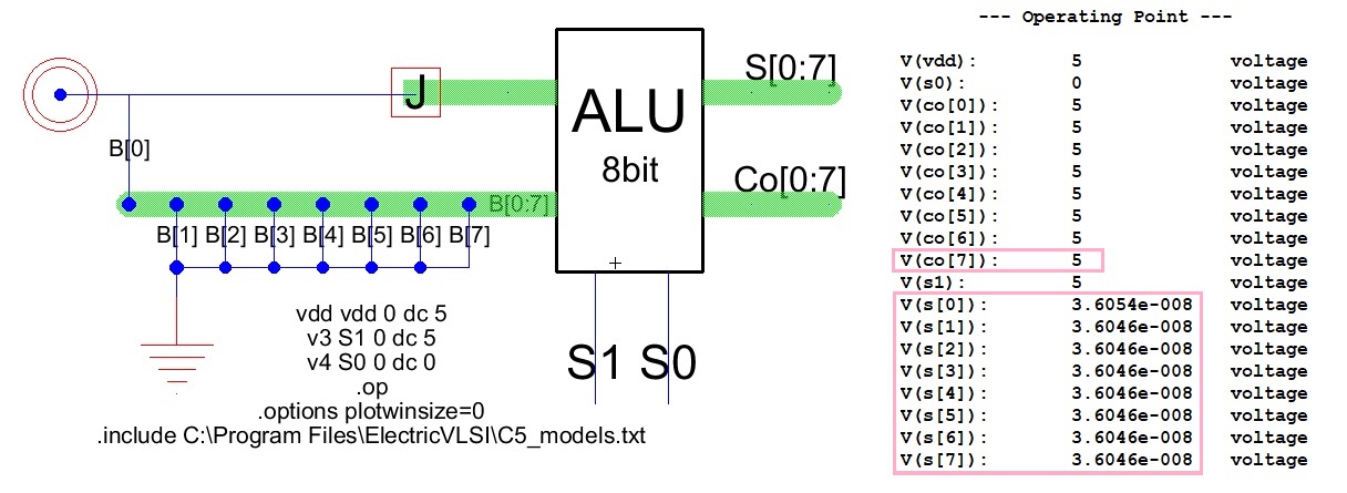
Figure 6. S0=0 & S1=1: Addition simulation.
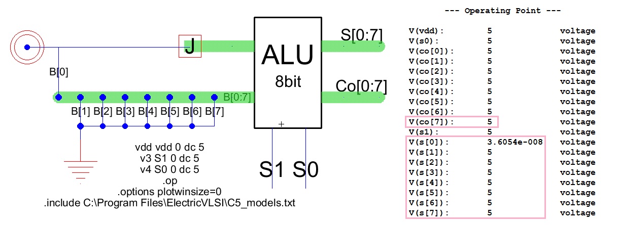
Figure 7. S0=1 & S1=1: Subtraction simulation.
5. Discussion
This lab was very interesting. It was much more complicated so
unsurprisingly I had much more issues than usual. I had mixed up the A
and B inputs for the FA at first but quickly remedied that once I did a
thorough check. I had a lot of trouble exporting only Co[7]. It
gave me part and wire errors. I ended up just exporting all Co[0:7]
ports in the Full Adder. Overall this was a very enjoyable lab and I
feel much cooler now that I have designed my own ALU.