ENGR338 Lab Spring 2021
Lab 3: Layout the R-2R DAC
Name: Audra Benally
Email: albenally1@fortlewis.edu
1. Title: Layout the R-2R DAC
2. Introduction: The purpose of this lab was to practice the layout
portion of ElectricVLSI. We started a whole new R-2R ladder DAC from
the last lab. An important new process was implemented with the use of
subcells. The subcells are used to make larger circuit layouts easier
to debug and fix.
3. Materials and Methods:
Materials:
- Computer
- LTSpice Software
- ElectricVLSI Software
Methods:
For this lab,
we remade the R-2R ladder than we made in the last lab. A very
important technique using subcells were used for this lab. The subcells
are smaller repeating parts of the main circuit which are made and then
DRC checked for any issues. Once any issues are addressed, the smaller
parts are used to make the rest of the circuit. Since the big circuit
is made of DRC clean subcircuits, any problems that arise can be
pinpointed to the most recent part of the circuit made. This will help
when we start making huge circuits that have a lot of different parts.
My subcircuits can be seen in figures 1 (schematic and icon) and 3
(layout). The subcell in figure 1 was used to make the R-2R ladder in
figure 2. The subcell in figure 3 was used to make the R-2R ladder in
figure 4. Because the subcells only contain repeating subcircuits, any
odd or unique parts are not included. So in figures 2 and 4, there is
an extra 10k resistor connected to the bottom of each ladder to
complete the R-2R ladder. Testing the circuit was a little tricky
because of the ideal ADC in the original simulation. So to test the
circuit I connected the new R-2R ladder DAC to the ideal ADC, as seen
in figure 5, and ran the spice code. The simulation ran the way it was
supposed to, as seen in figure 6, so the layout portion of the R-2R
ladder DAC is likely correct and accurate.
4. Results:
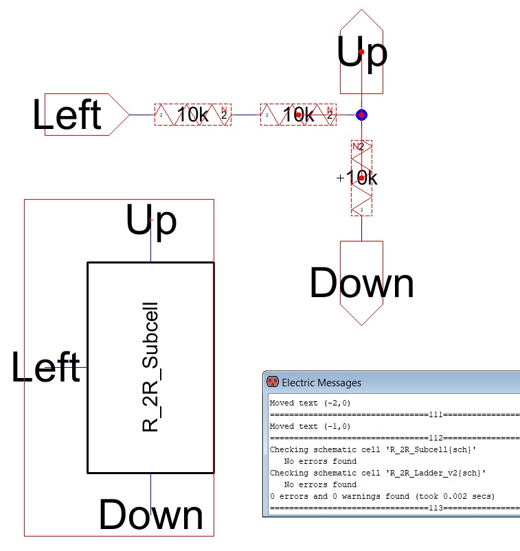
Figure 1.
Schematic and Icon of the R-2R subcell. The box shows the subcell is
DRC clean.
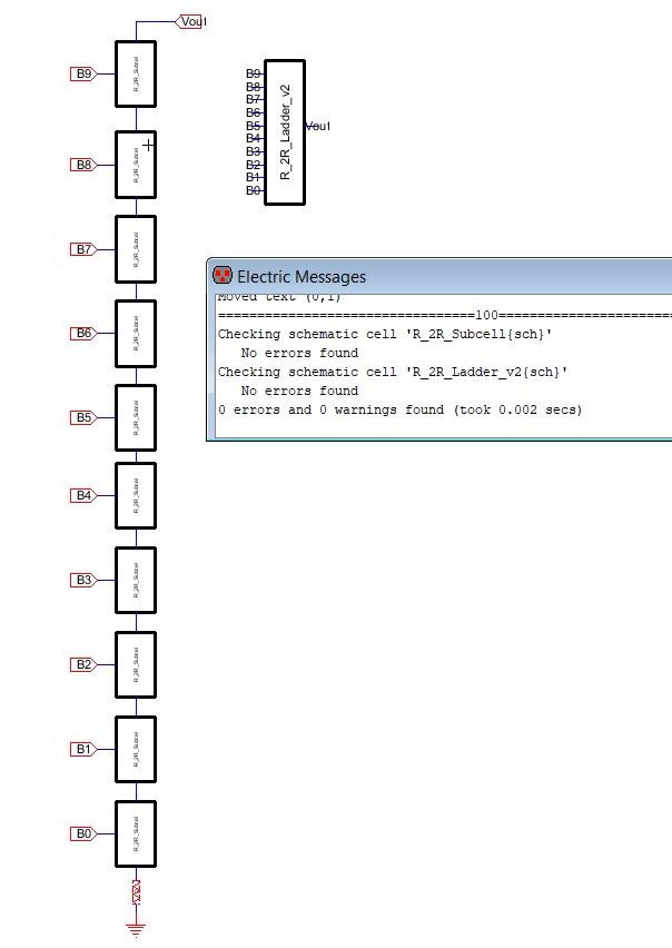
Figure 2.
R-2R ladder DAC version 2 with the subcells shown in Figure 1. The DAC
is DRC clean.
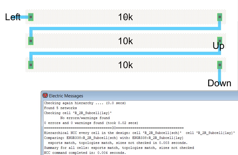
Figure 3. R-2R layout of the subcell. DRC and NCC show no errors.
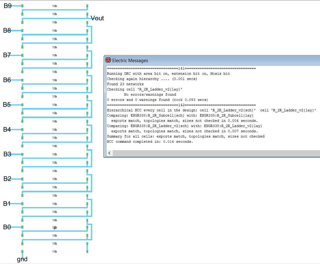
Figure 4.
R-2R ladder DAC v2 layout view made with the subcells shown in Figure 3. DRC and NCC tests show no errors.
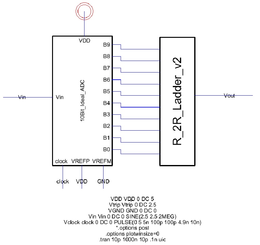
Figure 5.
R-2R Ladder DAC v2 connected to the ideal ADC for simulation.
Simulations results are shown in Figure 6.
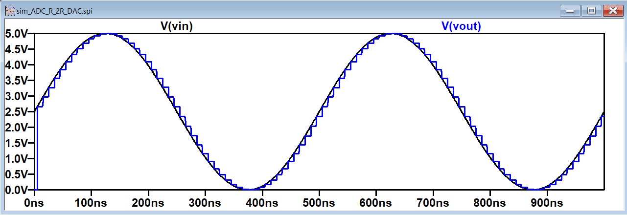
Figure 6.
Simulation results from the ideal ADC connected to the new R-2R ladder DAC.
5. Discussion
For this lab, the layout portion of the ElectricVLSI
software was reviewed and used to make another R-2R ladder DAC. The
schematic and icon view were remade using the subcell technique. All
portions of the scematic and icon were DRC appoved with no errors. The
schematic view of the R-2R ladder was made using the N-Well resistors.
I had a little trouble remembering which components to use but a quick
trip to the Tutorials on yilectronics.com cleared that right up. The
subcell was made first and was cleared with the DRC and NCC tests. Then
the rest of the ladder was made in the same manner as the icon and
schematic views. Because the ADC was ideal and could not be created in
layout view, the new R-2R DAC v2 icon was connected to the ideal ADC
and the spice code was simulated. Since the layout view was DRC and NCC
clean, the code working signified the layout was a success. My
simulation results can be seen in figure 6 and my connected ADC DAC
circuit can be seen in figure 5.