The Easy Pulse Sensor Module
The
Easy Pulse sensor is designed for hobby and educational applications to
illustrate the principle of photoplethysmography (PPG) as a
non-invasive optical technique for detecting cardio-vascular pulse wave
from a fingertip. It uses an infrared light source to illuminate the
finger on one side, and a photodetector placed on the other side
measures the small variations in the transmitted light intensity. The
variations in the photodetector signal are related to changes in blood
volume inside the tissue. The signal is filtered and amplified to
obtain a nice and clean PPG waveform, which is synchronous with the
heart beat [1].
Easy Pulse Version 1.1 uses a more robust sensor
(HRM-2155E) that operates in transmission mode and fits tight around
the fingertip, thereby it is less prone to motion.

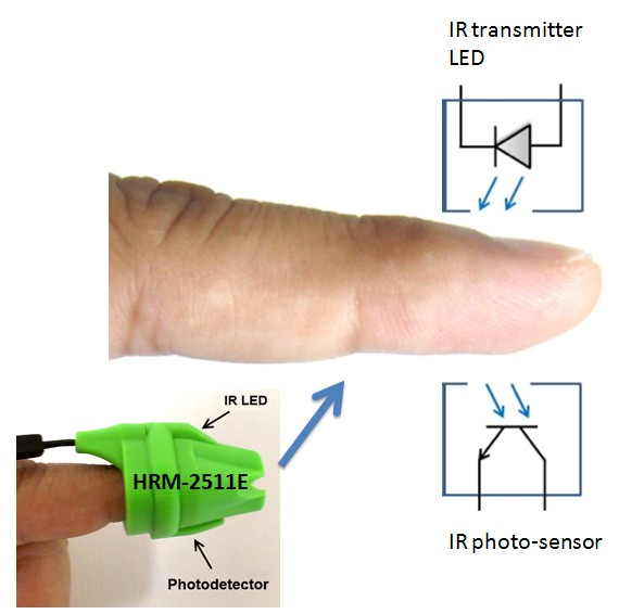
The
HRM-2511E sensor is manufactured by Kyoto Electronic Co., China, and
operates in transmission mode. The sensor body is built with flexible
Silicone rubber material that helps to keep the sensor tightly hold to
the finger. Inside the sensor case, an IR LED and a photodetector are
placed on two opposite sides and are facing each other. When a
fingertip is plugged into the sensor, it is illuminated by the IR light
coming from the LED. The photodetector diode receives the transmitted
light through the tissue on other side. More or less light is
transmitted depending on the tissue blood volume. Consequently, the
transmitted light intensity varies with the pulsing of the blood with
heart beat. A plot for this variation against time is referred to be a
photoplethysmographic or PPG signal. The following picture shows a
basic transmittance PPG probe setup to extract the pulse signal from
the fingertip.
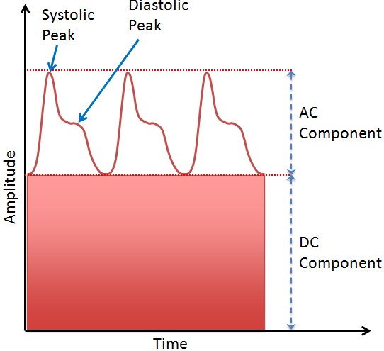
The
PPG signal consists of a large DC component, which is attributed to the
total blood volume of the examined tissue, and a pulsatile (AC)
component, which is synchronous to the pumping action of the heart. The
AC component, which carries vital information including the heart rate,
is much smaller in magnitude than the DC component. A typical PPG
waveform is shown in the figure below (not to scale).
Here are the features of Easy Pulse V1.1 sensor module.
- Uses HRM-2511E transmission PPG sensor for stable readings
- MCP6004 Opamp with rail-to-rail output capability for maximum signal swing (1.8V - 6V supply range)
- Separate analog and digital outputs
- Potentiometer gain control for the analog output
- Pulse width control for the digital output
- Additional test points on board for analyzing signals at different stages of instrumentation
Circuit diagrams
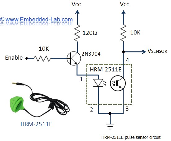
The
following circuit shows the ON/OFF control scheme for the infra-red
light source inside HRM-2511E. Note that the Enable signal must be
pulled high in order to turn on the IR LED. The photodetector output
(VSENSOR) contains the PPG signal that goes to a two-stage filter and
amplifier circuit for further processing.
The
PPG signal coming from the photodetector is weak and noisy. So we need
an amplifier and filter circuits to boost and clean the signal. In
Stage I instrumentation, the signal is first passed through a passive
(RC) high-pass filter (HPF) to block the DC component of the PPG
signal. The cut-off frequency of the HPF is 0.5Hz, and is set by the
values of R (=68K) and C (=4.7uF). The output from the HPF goes to an
Opamp-based active low-pass filter (LPF). The Opamp operates in
non-inverting mode and has gain and cut-off frequency set to 48 and
3.4Hz, respectively. In order to achieve a full swing of the PPG signal
at the output, the negative input of the Opamp is tied to a reference
voltage (Vref) of 2.0V. The Vref is generated using a zener diode. At
the output is a potentiometer (P1) that acts as a manual gain control.
The output from the active LPF now goes to Stage II instrumentation
circuit, which is basically a replica of the Stage I circuit. Note that
the amplitude of the signal going to the second stage is controlled by
P1. The Opamp used in this project is MCP6004 from Microchip, which is
a Quad-Opamp device and provides rail-to-rail output swing.

The
second stage also consists similar HPF and LPF circuits. The two-step
amplified and filtered signal is now fed to a third Opamp, which is
configured as a non-inverting buffer with unity gain. The output of the
buffer provides the required analog PPG signal. The potentiometer P1
can be used to control the amplitude of the PPG signal appearing at the
output of the buffer stage.

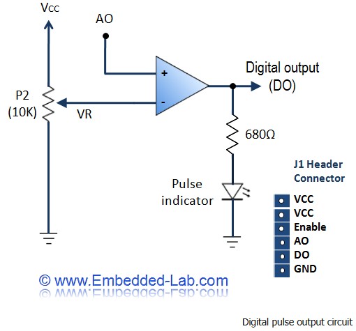
The
fourth Opamp inside the MCP6004 device is used as a voltage comparator.
The analog PPG signal is fed to the positive input and the negative
input is tied to a reference voltage (VR). The magnitude of VR can be
set anywhere between 0 and Vcc through potentiometer P2 (shown below).
Every time the PPG pulse wave exceeds the threshold VR, the output of
the comparator goes high. Thus, this arrangement provides an output
digital pulse synchronous to heart beat. Note that the width of the
pulse is also determined by VR. An LED connected to the digital output
blinks accordingly.
The following picture shows the Easy Pulse Version 1.1 board. The boards were manufactured by Elecrow
The
following picture shows a correct way of placing the HRM-2511E sensor
on the index finger. The IR LED illuminates the finger from the top.

Initially,
the potentiometers P1 and P2 are set to the midpoint. The sensor is
plugged into the index finger. Although the J1 header pins provides
final PPG output signal, it is possible to analyze the signal at
various intermediate stages through test pads TP1 and TP2. TP1 connects
to the VSENSOR signal pin, TP2 connects to the output from the Stage I
amplifier. Connect an oscilloscope channels to TP1, TP2, AO (4th pin of
J1), and DO (5th pin of J1) to observe the PPG waveforms at various
stages.
Signals from several nodes of the circuit.
VSENSOR:
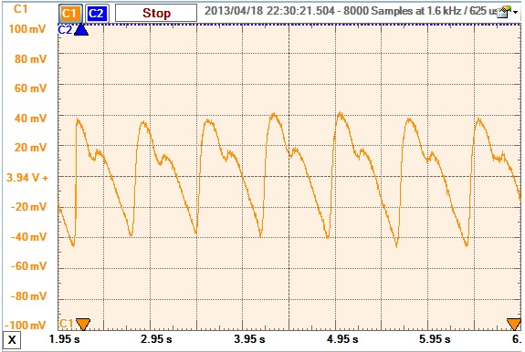
Stage I's output:
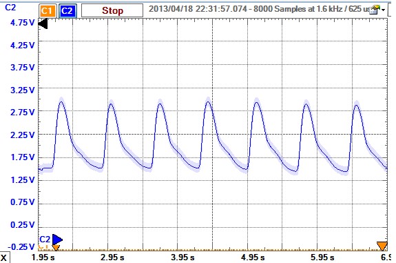
Final adjusted analog output AO:

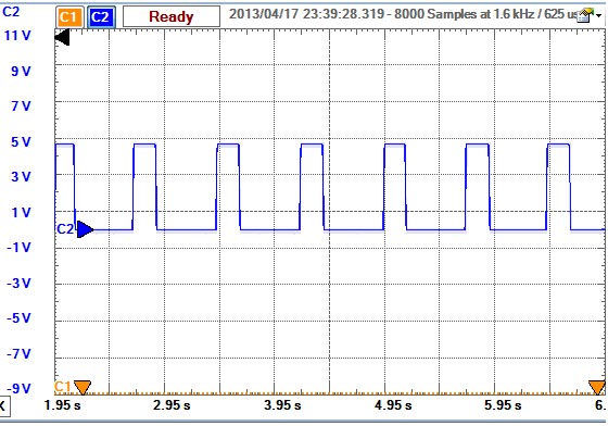
Final DO:
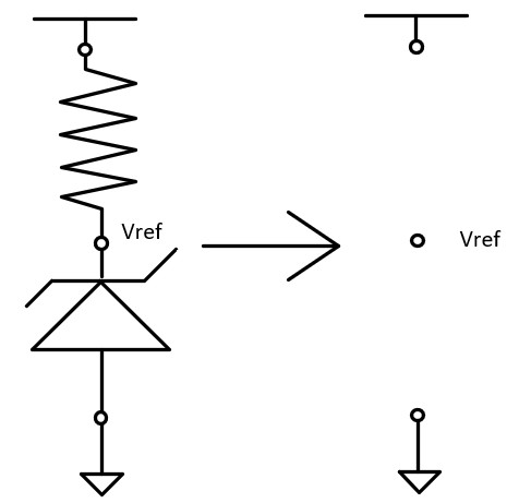
To
make it compatible with our XADC on the Basys3 board, the Op Amp's
power supply needs to be 1.8V (minimum for MCP6004), Vref needs to be
0.5V. A 0.5V reference can be provided by a dedicated reference IC or
use a voltage divider coupled with a voltage follower. Here, we will
directly supply it from a bench-top power supply.
Tasks:
Task
1: Assemble the Easy Pulse Sensor module. Use a bench-top power supply
to provide a 0.5V reference voltage to make sure that the AO output has
a bias at 0.5V and the largest voltage is less than 1V. VCC = 1.8V.
Show oscilloscope snapshots. (20 points)
Task 2: Design a simple voltage divider to reduce the DO to 0-1V. Show oscilloscope snapshots. (10 points)
Task
3: Use the oscilloscope to record your resting heart rate. Then,
briefly run or jump to raise your heart rate and take another
measurement to confirm that the device accurately detects both values.
Show oscilloscope snapshots. (10 points)
Reference
[1] Embedded-Lab Easy Pulse Sensor Lab