Spring 2026 CE433 Course Project: An Pulse Sensor ASIC Design
The
goal of this projet is to design a pulse sensor ASIC that includes an
off-chip amplifier/filter circuit, an on-chip ADC, Picoblaze CPU, and a
SPI module that directly communicates with an OLED display module (Pmod
OLED: 128 x 32 Pixel Monochromatic OLED Display).
The product diagram can be found below.
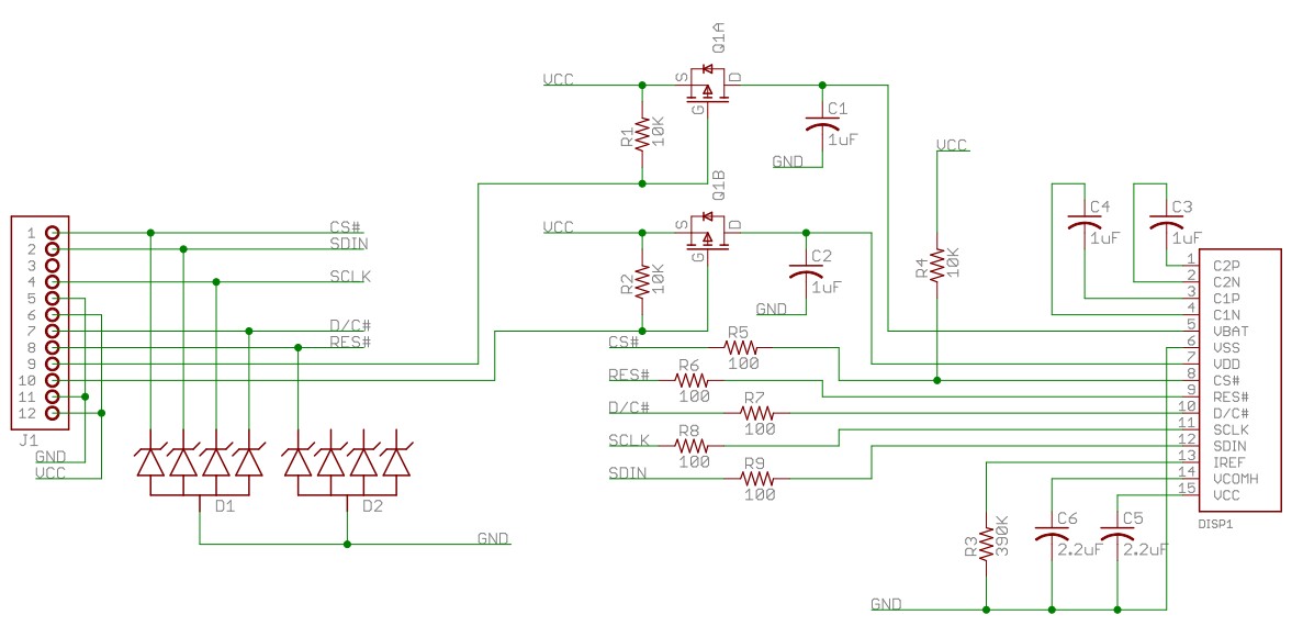
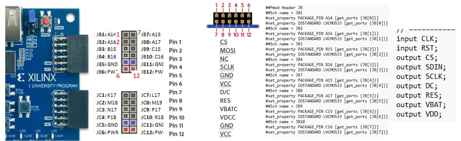
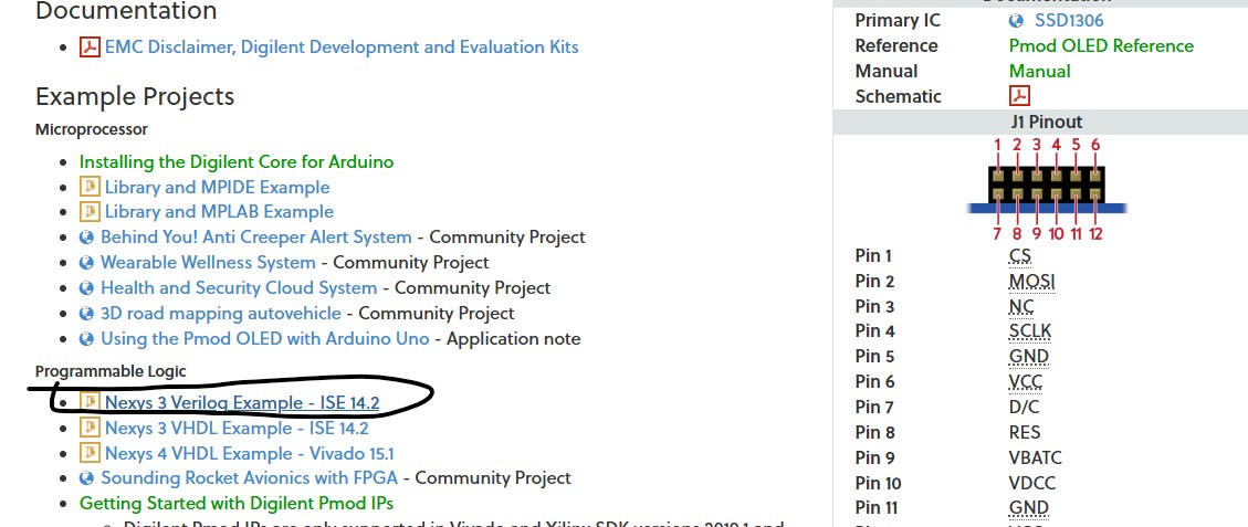
The Pmod OLED schematic can be found below.
The
pinout table can be found below. The CS, MOSI, and SCK pins are
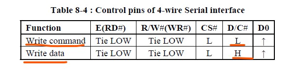
standard SPI pins. The fourth pin is D/C which is for Data/Command
Control.
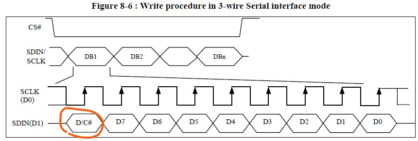
The D/C pin determines if the bytes are for the display or for the commands. The SSD1306 datasheet shows the details. From the datasheet, Section 8.1.3 MCU Serial Interface (4-wire SPI) describes how to use the fourth pin D/C. SDIN
is shifted into an 8-bit shift register on every rising edge of SCLK in
the order of D7, D6, ... D0. D/C# is sampled on every eighth clock and
the data byte in the shift register is written to the Graphic Display
Data RAM (GDDRAM) or command register in the same clock.
However,
for the Section 8.1.4 MCU Serial Interface (3-wire SPI), it requires
the D/C command to be sent along with data as D8. This requires a
different design of the driver in hardware and software to handle this
bit.
The Pmod OLED example page provided an example package
for the Nexys 3 board. We are using the Basys 3 board so some pins,
connections, and the constraint file may need changes to be compatible
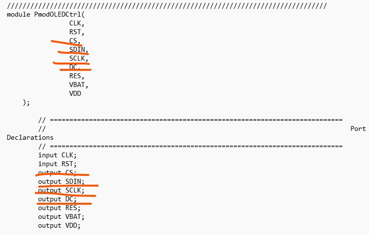
with the board. Open the top file of the design, the port
declaration tells that DC is a fourth pin so it must use the 4-wire SPI
timing diagram.
Bring
the Picoblaze core to this design and write an assembly code to measure
the digitized DO from the pulse sensor and count an average heart rate
and display it on the OLED display module.
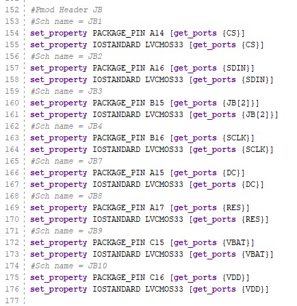
The pins of the PmodOLED is mapped to the JB pins as follows:
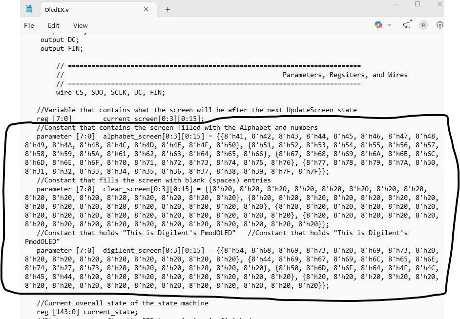
The
following content in OledEX.v must be replaced by the initial begin/end
block listed below since the format is not supported by Vivado.
// Row 3: blank for (c = 0; c < 16; c = c + 1) digilent_screen[3][c] = 8'h20; end
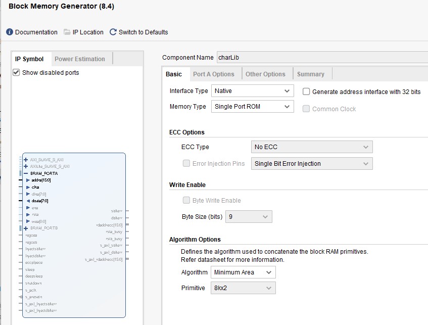
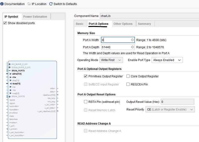
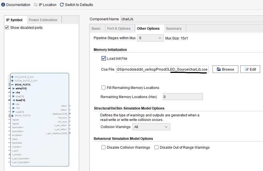
In
addition to the modifications above, you also need to create a memory
'charLib' to store the charLib.coe data. You can tell that charLib is
instantiated in the OledEX module
Here is the result of the example from Digilent.
Tasks: Task
1: Turn the PmodOLEDCtrl.v and the submodules into a Basys3 compatible
design and display any characters on the OLED to prove its
functionality. There is no Picoblaze involved, only use the code from
the example and make it Basys3 compatible. (50 points) Task
2: Add Picoblaze to the design, probe AO, read the XADC's output and
display the binary form on the on-board LEDs. (50 points) Task
3: Use assembly and Picoblaze for frequency measurement and display
heart rate on the OLED and at the same time, display realtime waveforms
on an Arduino serial plot. (50 points)