Data
types, operators, combinational logic
Relevant Digital Logic lecture videos:
Intro
to number systems
Number
conversion
Fractional
number conversion
2's
complement
The
Youtube lecture playlist of Digital Logic (CE241)
1.
Please review the number systems
Number
conversions among binary, decimal, octal, and Hexidecimal
1's and 2's
complement for negative numbers
2.
Fixed-Point Representation
Binary number to
be processed in a digital system may have a fractional
part. There are two methods to represent a binary number with integer
and fractional parts. These are fixed-and floating-point
representations.
Please print and
read through this PDF file for this section on the
textbook.
We can show an
unsigned fixed-point number (without a sign bit) as "UQp.q.", pay
attention to the two dots here.
U indicates the
unsigned bit notation; p represents integer, q represents the
fractional part.
The Q Format or the Q
Notation:
Example
1: (unsigned, UQ16.16) (U indicates Unsigned)
14.125(10) =
1110.001 (2) = 0000 0000 0000 1110.0010 0000 0000 0000
= 000E.2000
= 000E.2000
(UQ16.16)
Example
2: (signed, Q15.) (pay attention to the
dot there)
-14.125(10) = 1000 0000 0000 1110 (2) =
800E (losing the fractional part)
Example
3: (signed, Q15.16)
-14.125(10) =
1000 0000 0000 1110.0010 0000 0000 0000 (2) = 800E.2000
3.
Floating-Point Representation
The IEEE 754 standard for floating point representation
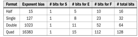
In floating-point representation, a binary number with fractional part
will be shown as N = (−1)^S × 2^E × F. Here, S stands for the sign bit,
E represents the exponent value, and F stands for the fractional part.
Then, floating-point number N is kept in memory as X = SEF.
Example
1:
14.125
in half precision/format:
14.125 (10) =
1110.001 = 1.110001 x 2^(3) = (-1)^0 x 2^(3) x 0.110001
=> S = 0
=> E = 15
+ 3 = 18 = 10010
=> F =
110001 0000
=> X =
SEF = 0 10010 110001 0000 = 0100 1011 0001 0000 = 4B10(16)
Example
2:
-14.125 in half
precision/format:
X = SEF = 1
10010 110001 0000 = 1100 1011 0001 0000 = CB10(16)
Example 3:
0.125 in Half
precision/format:
0.125 (10) =
0.001 (2) = 1.0 x 2^(-3)
=> S = 0
=> E =
15-3 = 12 = 01100 (must be 5 bits)
=> F =
0000000000 (must be 10 bits)
=> X =
SEF = 0 01100 0000000000 = 0011 0000 0000 0000 = 3 0 0 0 (16)
You can check
the results on this online conversion tool:
https://evanw.github.io/float-toy/
Verified:

Example
4:
3.141 in half
precision/format:
Use an online
converter to conver 3.141 to its binary form:
https://www.rapidtables.com/convert/number/decimal-to-binary.html
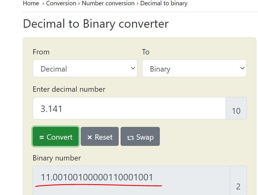
which is 1.1001
0010 0000 1100 0100 1 x 2^1
=> S = 0
=> E = 15
+ 1 = 16 = 10000
=> F =
1001 0010 0000 1100 0100 1, only keep 10 bits -
1001 0010 00
=> X =
SEF = 0 10000 1001 0010 00 = 0100 0010 0100 1000 =
4248
4.
ASCII Code
We do not only
process numbers in digital systems. For some
applications, we may need to handle characters and symbols as well. We
know that everything in a digital system is represented in binary form.
Therefore, characters and symbols should also be represented as such.
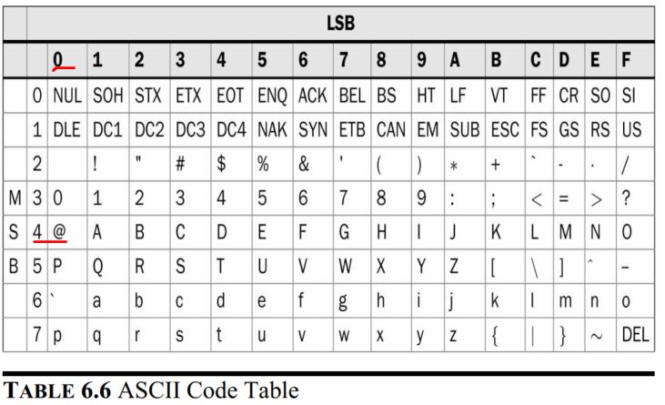
One way of representing characters and symbols in binary form is using
the ASCII code. ASCII stands for the American Standard Code for
Information Interchange.
To represent a
specific character (or symbol), its corresponding code
should be given. Let’s assume that we would like to represent the @
symbol. Using the following table, the corresponding ASCII code in
hexadecimal form will be 40 (pronounced as four zero).
5.
Net/Data types in Verilog
Net:
wire: a wire
connecting two elements
Variable:
reg: one-bit
data (a DFF)
integer: 32-bit
long
Data values:
0: logic 0
1: logic 1
x: don't care
z: high
impedance (open circuit or disconnected)
Constants and
parameters:
examples:
1'b0: a 1-bit
binary number 0
2'b10: a 2-bit
binary number 10
4'b10: the
binary number 0010
6'o75: 6-bit
octal number (6-bit means 6 binary bits)
8'hCA: 8-bit hex
number CA
8'd251: the
decimal number 251 is represented by 8 bits.
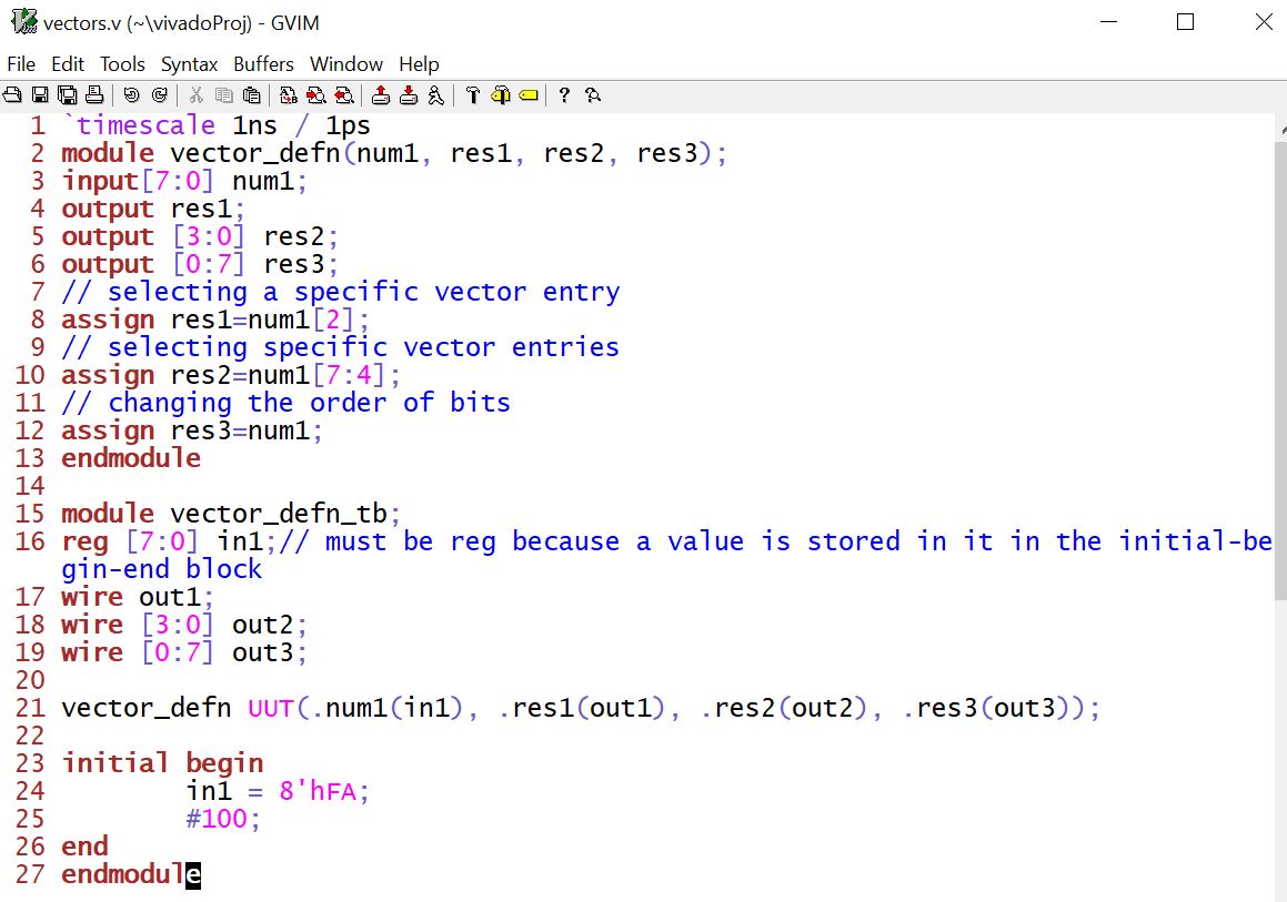
Vectors:
[N-1:0] prefix:
there are N net variable entries packed as a vector.
MSB and LSB are the N-1th and the zeroth entries respectively.
example: wire
[7:0] A. In this declaration, A is a wire data type with
8 bits. If you use 'A', it has all the 8 bits; if you use A[5:0] it
only take the lower 6 bits.
example: wire
[0:7] A. MSB becomes A[0], LSB becomes A[7].
A quick
simulation example from the textbook:
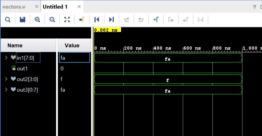
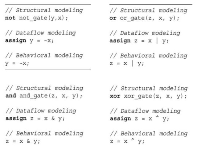
* Logic
gates
NOT, OR,
AND, XOR logic in Verilog:
6.
LUTs (look-up tables)
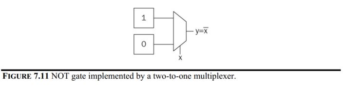
Combinational
circuits are implemented by LUTs in an FPGA. A generic
LUT is composed of a multiplexer and memory elements in its basic form.
We can take the NOT gate as an example of one-input combinational
circuit.
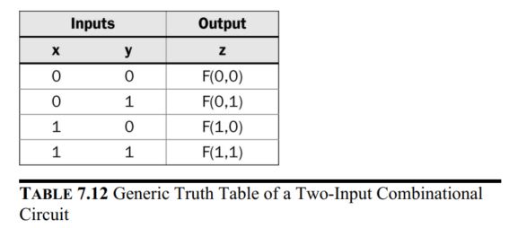
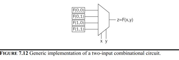
For two-input
combinational circuits, the truth table and the LUT look like this:
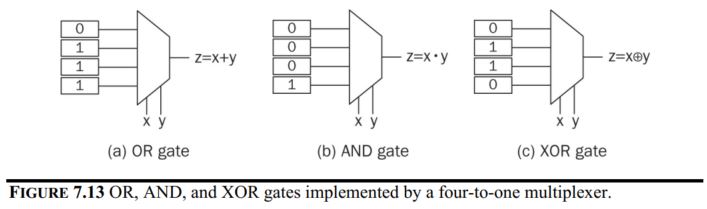
Examples of the
standard gates:
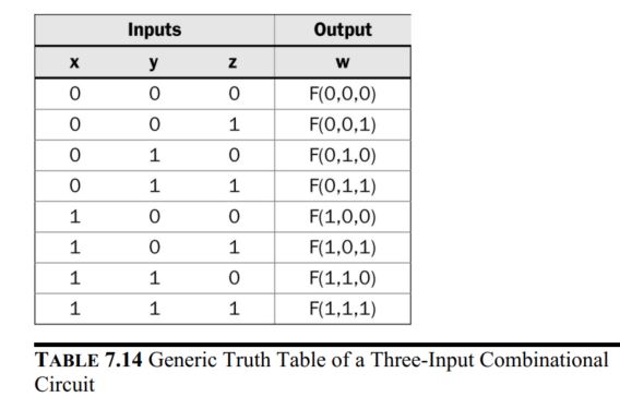
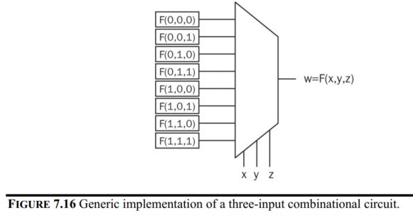
For three-input
combinational circuits, the truth table and the LUT look like this:
7.
Example of combinational logic design
7.1 A home alarm
system
- Four inputs from output of 4 sensors connected to 3 windows
and 1 door at home.
- One input as a switch to activate the entire system.
- One output to turn on the alarm.
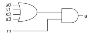
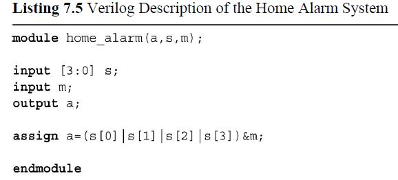
The Verilog
description of the alarm system.
Implement it on
the Basys3 board:
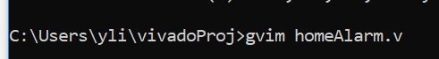
Create a new
'.v' file from the command line.
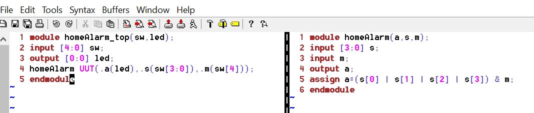
Once the gvim
window is opened, type the homeAlarm module into it.
Also, open a new window using ':vert new homeAlarm_top.v' command.
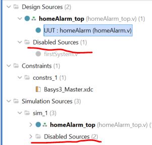
In Vivado,
disable the previous sources buy right-clicking the file and
select 'Disable File'. Also, add the two source files you just created.
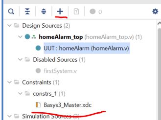
Add the
constraint file 'Basys3_Master.xdc' using the '+' button. (you can
download it from here. Unzip it before adding
it to Vivado).
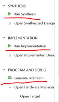
Run the
Synthesis, Implementation, and Bitstream Generation respetfully.
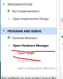
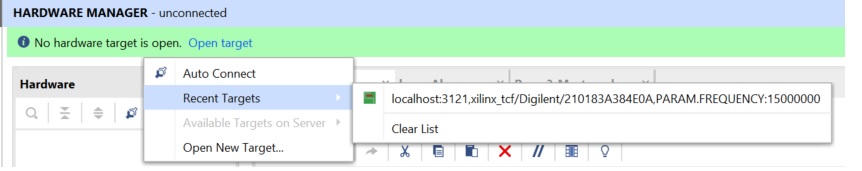
Then click 'Open
Hardware Manager' to open a new target if it is the
first time to use the Basys3 Board on your computer. Otherwise, open a
recent target.
Results:
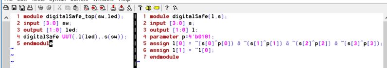
7.2
Digital safe system
There is a
predefined password stored in the system. Every bit of the input must
match the stored bits.
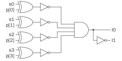
Use XOR to check
if every bit matches. If it does, XOR gate outputs
0's. Invert the 0's to get 1's which are used as the input to one
4-input AND gate.
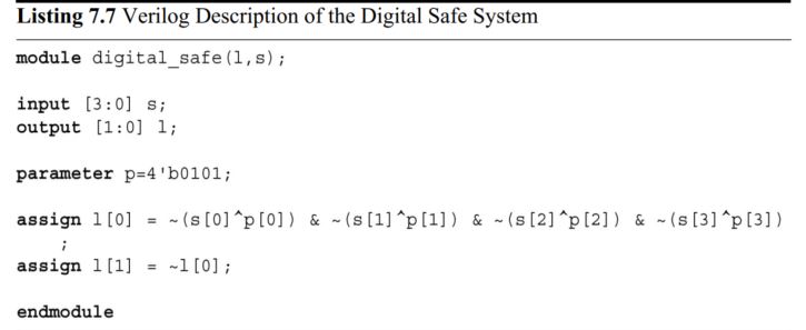
The Verilog
script:
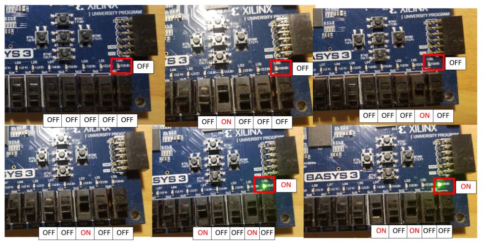
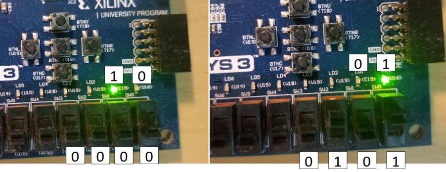
Implement this
on the Basys3 Board:
When the input
is 0101 (MSB - LSB), led[0] lights up, otherwise, led[1] lights up.
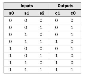
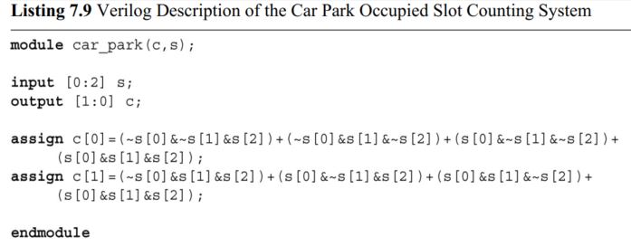
7.3
Car parking occupied spots counting system
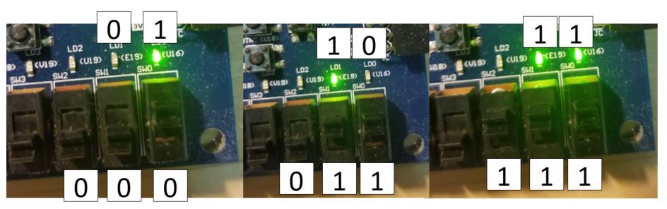
S0, S1, and S2
are the three spots on the parking lot. Output C1C0 is
the 2-bit binary number that represents the count of the occupied
spots.
The truth table
of the logic:
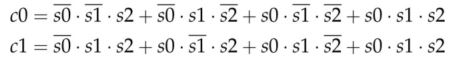
From the truth
table, the following logic expression was created:
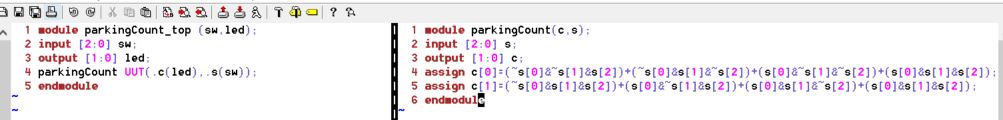
The Verilog
script:
Type the
following script in gvim and add them to the project.
Implement it on
the Basys3 Board:
-------------------
Tasks
1.
Work on the following problems: (16 points)
a.
What are the fixed point representations of the following decimal
numbers? Display your calculations and results in your report.
20.25 in UQ16.16
128.5 in UQ16.16
0.125 in UQ.16
-38.125 in Q15.16
-50.0625 in
Q15.16
b. What are the
floating point representations of the following decimal
numbers? Display your calculations and results in your report.
0.141 in half
precision/format
3.625 in half
precision/format
-15.25 in half
precision/format
2.
Repeat the simulation work in Section 5. Include the snapshots of the
code and simulation results in your report. (10 points)
3.
Repeat all the FPGA experiments in Section 7 (Home alarm system, digital safe system, and car parking system). Include
the snapshots of the code and FPGA demo video links in your report. (Use
the ':vert new homeAlarm_top.v' command to open a new Vim window for
your top module). (30
points)