Remote
decoder model number and carrier frequency. The carrier frequency for
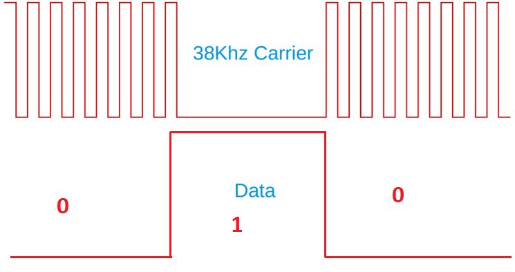
an infrared (IR) decoder is the frequency used to modulate IR pulses.
The most common carrier frequency for consumer IR devices is 38 kHz,
but other frequencies are sometimes used, such as 40 kHz, 56 kHz, 36
kHz, or 39.2 kHz.
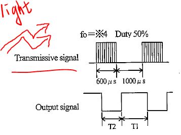
An
optical 1 results in a 0 at the output of the receiver. Another
datasheet shows more information about a similar part - Part number of
the IR receiver: GP1UW70QS,Link to the datasheet.
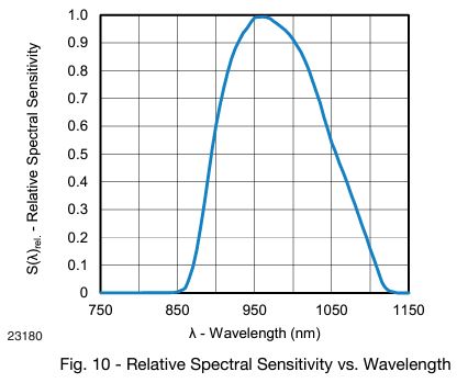
Receiving wavelength. What wavelength of light(nm) is the remote control decoder most sensitive to?
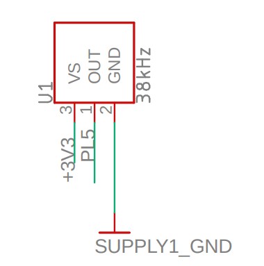
IR decoder board connections.
IR LED specs:
Emmsion spectrum. Datasheet can be foundhere. What is the peak emitted wavelength of this LED?
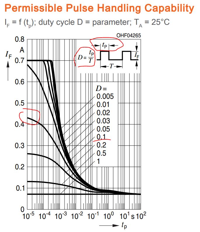
Permissible Pulse Handling Capability. First, we need to answer this following question:
Why not have the LED just on and off?(selected materials fromthis site)
1.
This lets the LED cool off. IR LEDs can take up to 1 Amp (1000
milliamps!) of current. Most LEDs only take 20mA or so. This means IR
LEDs are designed for high-power blasting BUT they can only take it for
a few microseconds. By PWM'ing it, you let the LED cool off half the
time. 2.
Another reason is that the TV will only listen to certain frequencies
of PWM. So a Sony remote at 37KHz won't be able to work with a JVC DVD
player that only wants say 50KHz. 3.
The most important reason is that by pulsing a carrier wave, you reduce
the effects of ambient lighting. The TV only looks for changes in light
levels that occur around 37–38 kHz.
From the following diagram, you can find the maximum permissible current when the duty cycle is 10% or 0.1.
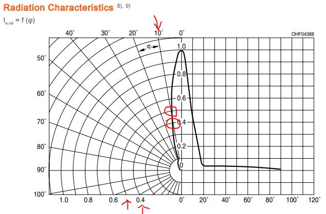
Radiant intensity map. What is the Relative Radiant Intensity of light emitted by the LED when viewed 10° off center?
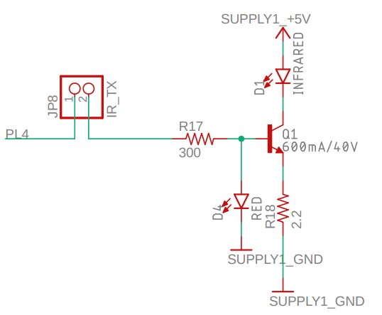
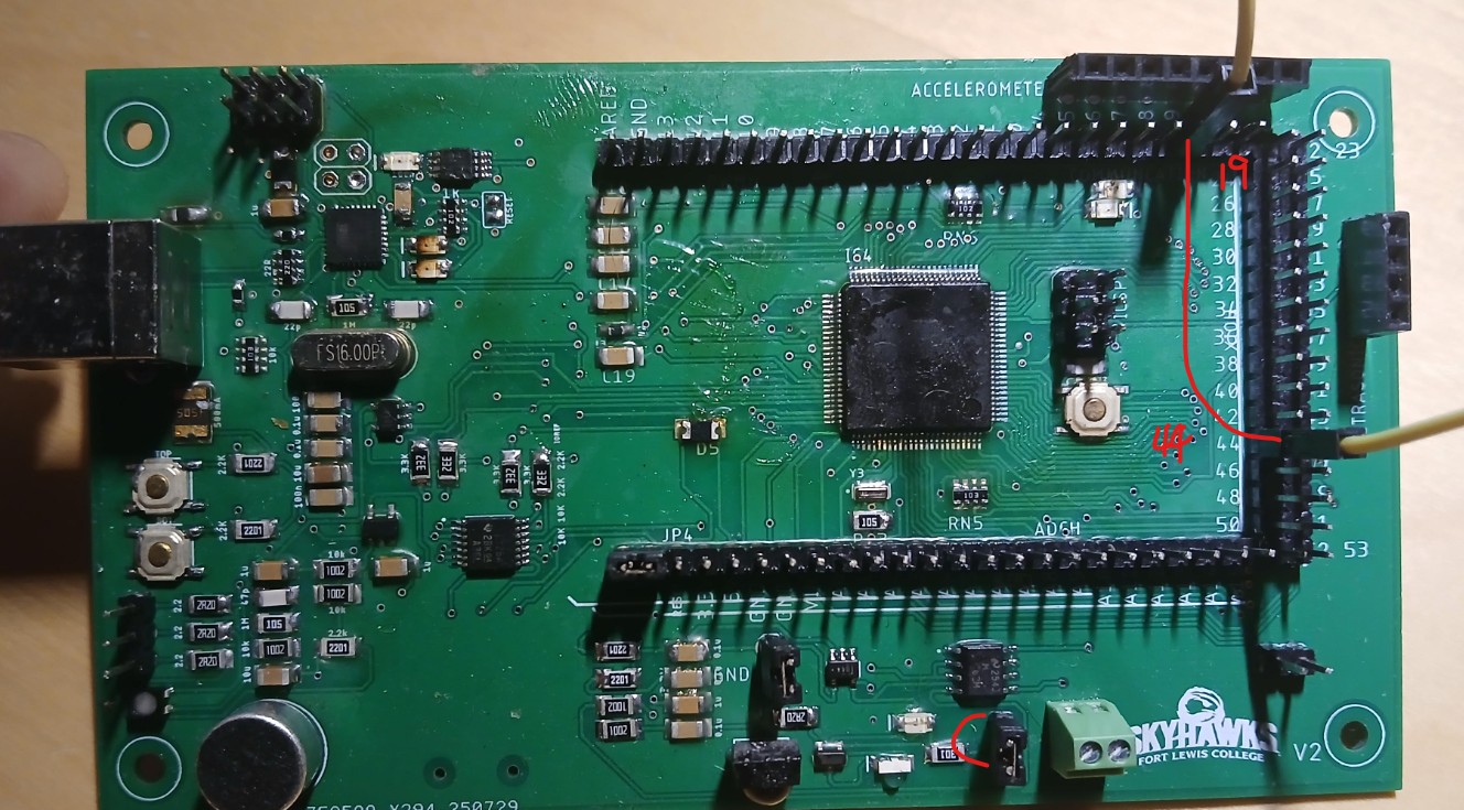
Which pin drives this IR LED? PL4 is associated with OC5B so it's a TIMER5's PWM module. .
Task 1 Use IR to send and receive a letter that was programmed into the code.
OC5B
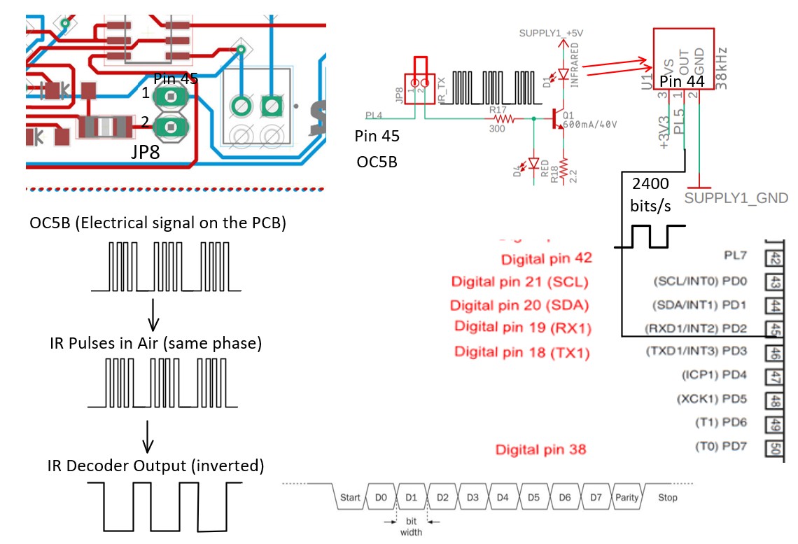
is the PWM output pin that we are going to use. Putting a little jumper
on the top of JP8, the PWM pulses could be delivered to the Base of the
BJT. IR emission from the LED will be received by the decoder, a
digital signal will be available at the PL5 pin (Pin 44). However, we
don't want to use that pin as the digital input to the MCU. Place
a female-female jumper wire to connect Pin 44 and Pin 19. Pin 44 is the
digital output of the decoder, Pin 19 is the digital input of the UART
Module 1.
38
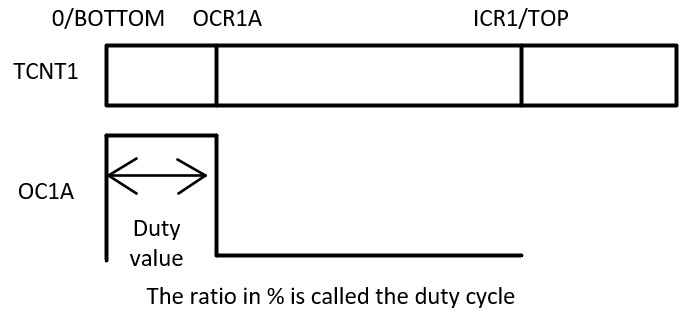
kHz pulses need a 1/38k = 26.3 or 26 us. So the PWM is 26 us. 1:1
prescaler is not the best choice but it is fine (lower duty cycle
resolution). What is
the duty value to make 10% duty cycle happen? - 10% * 26 us = 2.6 us.
N is the prescaler.
This first task doesn't use an ISR to send or receive. We use the TIMER5 module for PWM and the TIMER3 module to create a 9600 bits/s envelope for UART1 (or Serial1). Therefore,
to let Rx receives a 0, you need to turn on the PWM; to let Rx receives
a 1, you need to turn off PWM. The bit rate we are going to use is 1200
bits/s for UART1 (Serial1) in Task 1; In Task 2 and 3, we'll change it
to 2400 bits/s. When ISR is not used, you need to manually clear
the overflow flag by writing a 1 to the TOV3 bit, which is TIFR3 |= (1
<< TOV3); Since ISR is not used, you don't need to enable TIMER3's interrupt - TIMSK3 |= (1 << TOIE3);
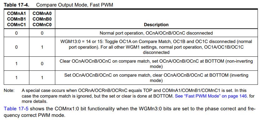
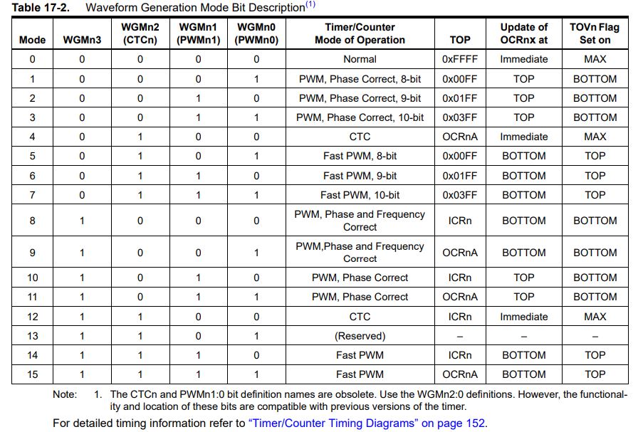
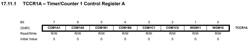
Use the following code snippet to turn on PWM:
TCCR5A |= (1 << WGM51) | (1 << COM5B1);
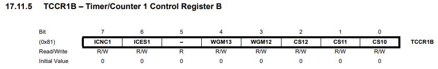
TCCR5B |= (1 << WGM52) | (1 << WGM53) | (1 << CS50);
OCR5B = LED_ON;
Use the following code snippet to turn off PWM:
TCCR5A &= ~(1 << COM5B1); Interestingly, it is not OCR5B = 0 to turn it off.
You'll need to use the following block as a routine to create a time delay using TIMER3:
TCNT3 = 0x10000 - bitPeriod[baudRateSelected]; // set up the count for
a certain amount of time delay
TCCR3B |= (1 << CS30); // Prescaler 1:1 and turn on the timer
while ((TIFR3 & (1 << TOV3)) == 0); // Wait here when it is
counting
TCCR3B = 0x00; // Turn off the timer when the timer is up
TIFR3 |= (1 << TOV3); // Write a 1 to TOV3 to clear the TOV3 bit
so the timer can be re-opened in the next cycle
Use the following code snippet to go through all the bits in a byte (the letter's ASCII code). mask = 0b00000001; while (mask != 0) {
if (letter & mask) {
xxxxxxxxxxxxxxxxxxxxx; // Your code here, turn off the emitter } else {
xxxxxxxxxxxxxxxxxxxxxxx
xxxxxxxxxxxxxxxxxxxxxxx
xxxxxxxxxxxxxxxxxxxxxxx // Your code here, turn on the emitter }
mask <<= 1;
Case 'R' is given:
if (Serial1.available()>0) {
char received =
Serial1.read();
Serial.print("Just read in ");
Serial.print(received);
Serial.print(" from Serial1");
Serial.print(" (0x");
Serial.print(received, HEX);
Serial.println(")"); } else {
Serial.println("Nothing received from Serial1"); } break;
You'll need to design your Case 'S' to send the Start bit, the data byte, and the Stop bit through the emitter.
Task 1 grading rubric: (Your
code should be built using the examples provided in this tutorial and
must not rely on entirely new programming methods found through AI) 1. #define and variable declaration (10 points) 2.
The void setup() function (10 points). Serial1 baud rate 1200 bits/s. Place TIFR3 |= (1 <<
TOV3); in your setup function if the first letter received is incorrect. 3. Case 'S'. (30 points)
Task 1's demo video:
Task 2 Repeat Task 1 Using the TIMER3 ISR to Send
When it enters ISR, the TOV3 bit is cleared automatically so TIFR3 |= (1 << TOV3); is not needed.
ISR needs to be enabled in the setup() function: TIMSK3 |= (1 << TOIE3);
In
Case 'S', set a flag to be true so the next time it enters the ISR, it
doesn't stay at the TX_IDLE state but the TX_DATA_BITS state.
At the end of the ISR, TIMER3's TCNT3 register needs to be re-configured.
Task 2 grading rubric: (Your
code should be built using the examples provided in this tutorial and
must not rely on entirely new programming methods found through AI.) 1. #define and variable declaration (10 points) 2.
The void setup() function (10 points). Serial1 baud rate 2400 bits/s. 3. Case 'S'. (30 points). Add delay(10) to your 'S' or 'R' cases if data instability is observed. 4. The ISR. (50 points) Task 2's demo video is not provided since it does the same job.
Task 3 Use IR to transmit a message (string)
In
order to have better control of Serial 1, we need to bypass the
embedded function Serial1.begin(). This function sets up the baud rate,
enable receive and trasmitt interrupts, and defines the data length.
Now, we need to configure these operations using Arduino's control
registers.
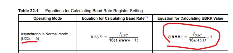
The
UBRRn register sets up the baud rate. The user must follow the
following equation to assign the baud values to the 12-bit UBRRnH/L
registers
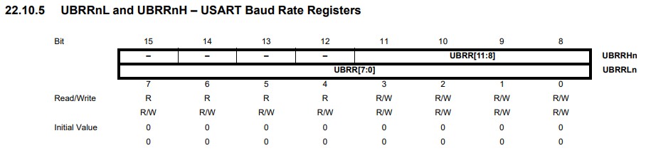
There
are two bytes (16 bits) allocated for the UBRR registers but only the
lower 4 bits of UBRRHn and the entire byte of UBRRLn are used.
Therefore, you need the following two lines to assign your baud values
to these registers: UBRR1H = BAUD_VALUE >> 8; UBRR1L = BAUD_VALUE;
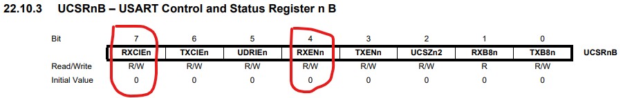
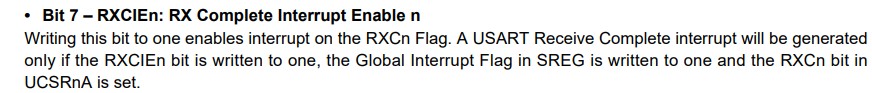
RXCIEn
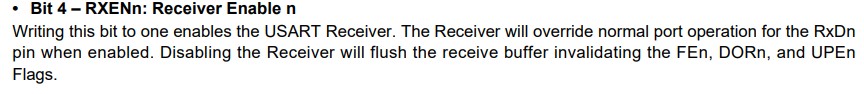
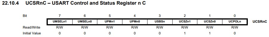
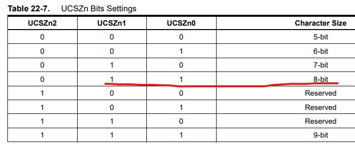
The UART1 initialization for this example is as follows:
UBRR1H = BAUD_VALUE >> 8; UBRR1L = BAUD_VALUE; // Enable receiver, transmitter, and RX Complete interrupt UCSR1B = (1 << RXEN1) | (1 << RXCIE1); // Set frame format: 8 data bits, no parity, 1 stop bit UCSR1C = (1 << UCSZ10) | (1 << UCSZ11);
We use 2400 bits/s as the baud rate, what is BAUD_VALUE? (16M/16*2400)-1
Fort
Case 'm', the software should display a prompt instructing the user to
type a message. The message should be placed after two address bytes.
The two dddresses are preset sudo addresses. 'Pressing enter when done'
means the address ends with a return character '\r' and this will be
detected as the end of the message body.
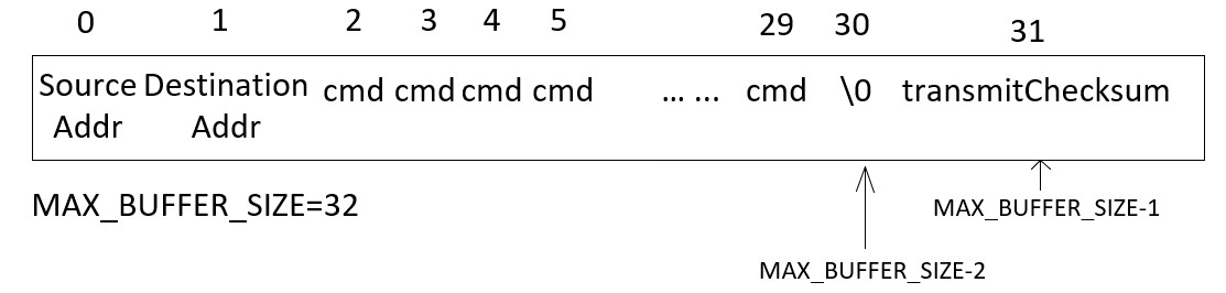
This is how the case 'm' assembles the message packet.
case 'm':
Serial.println("Enter the message, hit return when done."); Serial.print(">");
transmitIRBuffer[0] =
transmitSourceAddr;
transmitChecksum =
transmitSourceAddr;
transmitIRBuffer[1] = transmitDestinationAddr; // Generally unprintable transmitChecksum += transmitDestinationAddr; while(Serial.available()==0); i=2;
while ( ((cmd = Serial.read()) != '\r') && (i <
MAX_BUFFER_SIZE-2)) { sprintf(buff,"%c",cmd); Serial.print(buff);
transmitIRBuffer[i++] = cmd; transmitChecksum += cmd;
if (i >= MAX_BUFFER_SIZE-3) {
sprintf(buff,"maximum message length of %d characters
reached\r\n",MAX_BUFFER_SIZE-4);
Serial.println(buff); }
while(Serial.available()==0);
}
transmitIRBuffer[i] =
'\0';
// Null terminate string
transmitIRBuffer[i+1] =
transmitChecksum; // Checksum of
the message Serial.println("\r\nMessage entered"); break;
For Case 'S', it turns on certain flags for the ISR: case 'S': transmitStart = true; while (transmitStart == true); Serial.println("Transmitted");
sprintf(buff,"Message: %s", transmitIRBuffer+2);// Treat the array name
'transmitIRBuffer' as a pointer points to the first element
// +2 will point to the first message character in the array, then it
directly prints out the string and ends at '\0'. Serial.println(buff);
sprintf(buff,"Checksum computed: %d", transmitChecksum); Serial.println(buff);
sprintf(buff,"Sender address: %d",transmitSourceAddr); Serial.println(buff);
sprintf(buff,"Target address: %d",transmitDestinationAddr); Serial.println(buff); break;
For
Case 'R', it computes the Checksum (the summation of all received
cmd's ASCII value), prints out each single byte from the message
packet. case 'R':
if (receiveNewMessage == true)
{
receiveSourceAddr = receiveIRBuffer[0];
receiveChecksum =
receiveIRBuffer[0];
receiveDestinationAddr = receiveIRBuffer[1];
receiveChecksum +=
receiveIRBuffer[1];
i = 2;
while (receiveIRBuffer[i] != '\0') {
receiveChecksum += receiveIRBuffer[i];
i += 1; }
transmitChecksum =
receiveIRBuffer[i+1];
Serial.println("Received");
sprintf(buff,"Message:
%s",receiveIRBuffer+2); Serial.println(buff);
sprintf(buff,"Checksum computed: %d",transmitChecksum); Serial.println(buff);
sprintf(buff,"Checksum received: %d",receiveChecksum); Serial.println(buff);
sprintf(buff,"Sender address:
%d",receiveSourceAddr);
Serial.println(buff);
sprintf(buff,"Target address: %d",
receiveDestinationAddr);
Serial.println(buff);
receiveNewMessage = false; } else {
Serial.println("No message, receiveNewMessage = false"); } break;
Here is the template for the two ISRs. Task 3 grading rubric: (200 points) 1. State TX_START_BITS, 50 points 2. State TX_DATA_BITS, 50 points 3. State TX_STRP_BITS, 50 points 4. TCNT3 timer reset, 10 points 5. USART ISR, state RX_DATA_BYTES, 20 points 6. USART ISR, state RX_CHECKSUM, 20 points