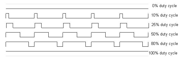
Pulse Width Modulation Pulse
Width Modulation, or PWM, is a technique for getting analog results
with digital means. Digital control is used to create a square wave, a
signal switched between on and off. This on-off pattern can simulate
voltages in between the full Vcc of the board (e.g., 5 V on UNO, 3.3 V
on a MKR board) and off (0 Volts) by changing the portion of the time
the signal spends on versus the time that the signal spends off. The
duration of "on time" is called the pulse width. To get varying analog
values, you change, or modulate, that pulse width. If you repeat this
on-off pattern fast enough with an LED for example, the result is as if
the signal is a steady voltage between 0 and Vcc controlling the
brightness of the LED.
PWM
has several uses: Dimming an LED Providing an analog output; if the
digital output is filtered, it will provide an analog voltage between
0% and 100%. Generating audio signals. Providing variable speed control
for motors. Generating a modulated signal, for example to drive an
infrared LED for a remote control.
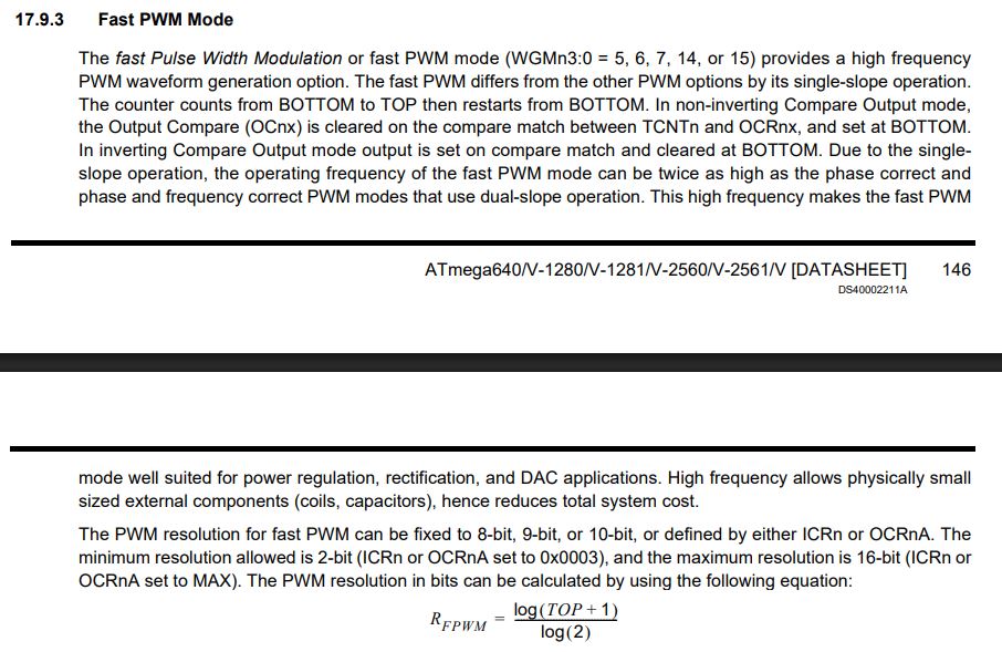
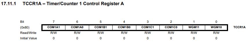
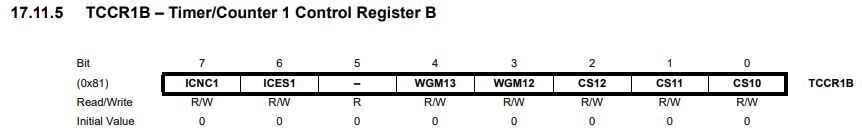
Task 1: Use the serial monitor to control LED brightness (20 points) For the Skyboard, there are several modes for PWM and we are picking up the Fast PWM Mode for Task 1.
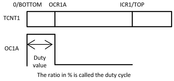
The
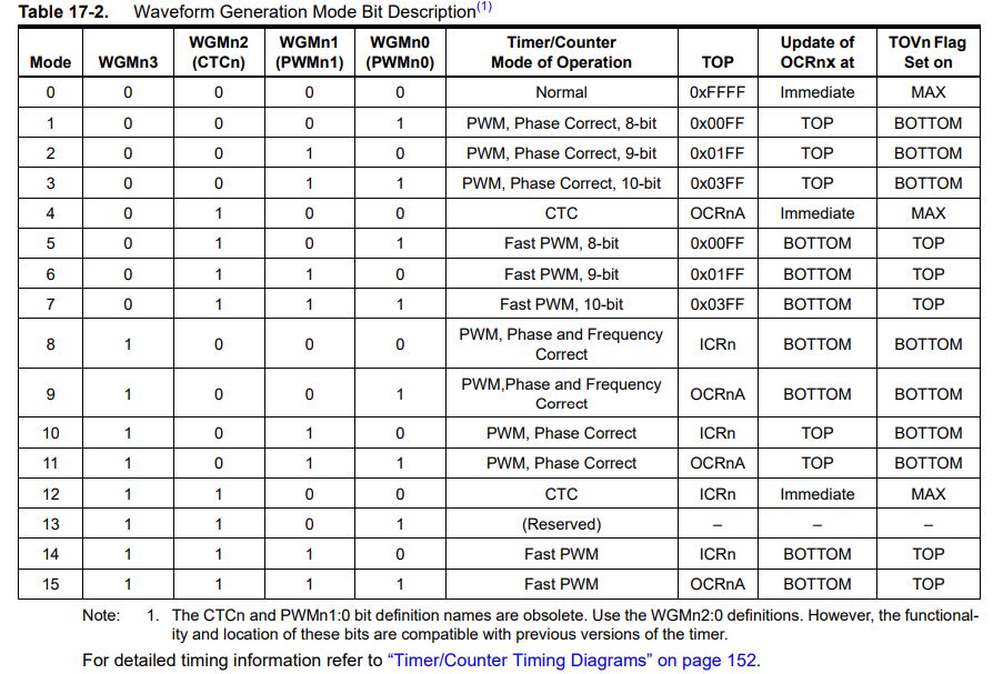
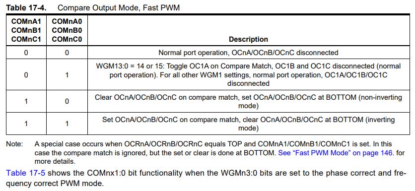
example above uses the Mode 14 in Table 17-2, and Mode 2 in Table 17-4.
Refer to the description on Page 146, the non-inverting mode pulls the
OC1A pin (Pin 11 in this example) to 0 when TCNT1 counts up to OCR1A
from 0 (BOTTOM), then it pulls up to 1 when it reaches BOTTOM again. It
reaches BOTTOM again when it reaches TOP and clears up itself so it is
pulled up to 1 when it reaches ICR1. The following diagraph shows how
it works.
Here is the video demo for Task 1.
Task
2: The color cube (80 points - setup() 20 points, case 'a' 5 points,
ISR colorTour true 20 points, ISR colorTour false 20 points, TCNT2
value calculation 15 points).
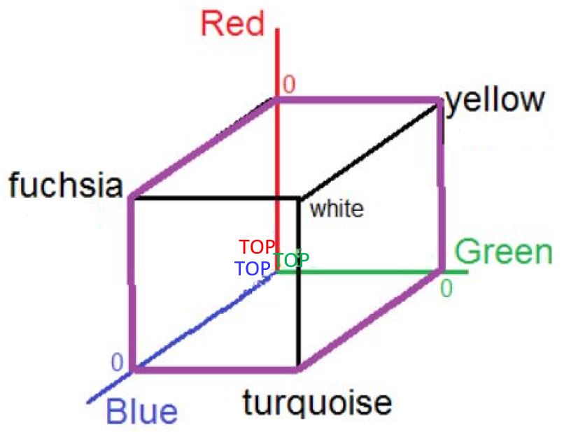
The
goal is to tour all the six colors of the color cube using PWM and a
TIMER ISR. The purple lines show the sequence of the color tour. You
can start with any of these colors but must follow the line to change
the color. Because the LEDs have active 0 connections, giving a 0 to
the pin will turn them fully on and give them a 255 will turn them off.
Here is the sequence of the tour: Red
Fuchsia Blue
Turquoise
Green
Yellow Red (0,255,255) -> (0,255,0) -> (255,255,0) -> (255,0,0) -> (255,0,255) -> (0,0,255) -> (0,255,255)
Here is the template
you can start with. To simplify the program development, we are going
to use the analogWrite() function to send PWM to the LEDs and we are
going to use TIMER2 ISR to control the intensity of each color channel.