SPI
Introduction Serial Peripheral Interface (SPI) communication was used
to connect devices such as printers, cameras, scanners, etc. to a
desktop computer; but it has largely been replaced by USB. SPI is still
utilized as a communication means for some applications using displays,
memory cards, sensors, etc.
First,
we need to know that for SD cards, a page is the minimum unit for
writing operations. Most of the SD cards have 512 bytes for a page. In
this lab, you will see 'block' instead, please note that 'block' in
this lab means 'page' in general. You must write the entire page to the SD card each time.
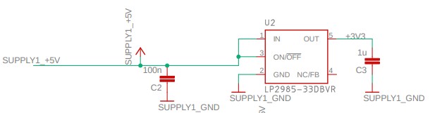
The SD card module on the Skyboard:
The
bottom one is the SD card's socket soldered on the board. The chip on
the top is a level shifter. The microSD card requires 3.3 V but the
Arduino chip outputs a 5V logic. The 3.3 V power is supplied by the following chip:
On
the SD card socket symbol in the schematic, the pin SDI_P3 is the input
pin to the SD card, SDO_P7 is the output pin of the SD card. SDO is
shorted to the SPI input on the Mega chip - MISO. SDI is shorted to
Mega's SPI outout - MOSI. The
PB0 - PB3 pins are the pins of the Mega chip. The A ports of the level
shifter are at the 5V logic, the Y potrs are at the 3.3 V logic.
The SPI ports of the Mega chip:
The
PB ports should always be placed at the 5V side of the level shifter
and the SPI ports of the SD card should be placed at the 3.3 V side. On
the Skyboard, PB3 and MISO_CARD should be swapped. The reason that it
still works is that the SDO pin's logic 1 is at 3.3 V is also
recoganized as a logic 1.
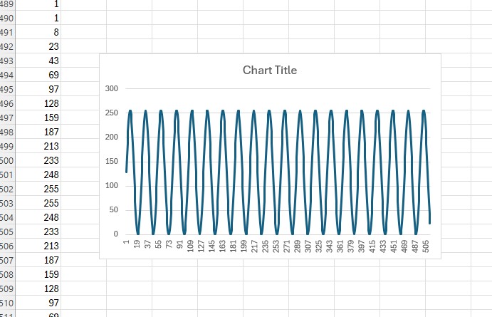
Task 1: (30 points) Download the SdFat library to your Arduino IDE. If you don't have an SD card on the Skyboard, request one from Dr. Li. Go to Sketch - Include Library - Manage Libraries. Search for 'sdfat', scroll down to find the 'SdFat' library then install it.
Copy
and paste this example code and download it to your Skyboard. The
serial monitor should show that the verification is successful and
it should print numbers from 0 - 255 twice.
You
will see a lot of online examples uses the SD.h and the SPI.h
libraries. It requires the user to open a file on the SD card first
before write and read to the card. You could use this library if your
project has a slow sampling rate. For faster sampling rate, writing,
and reading, using the SdFat libarry to write/read blocks of data with
the SD card is the way to go. Keep in mind that a block/page is 512 bytes for most of the modern SD card devices.
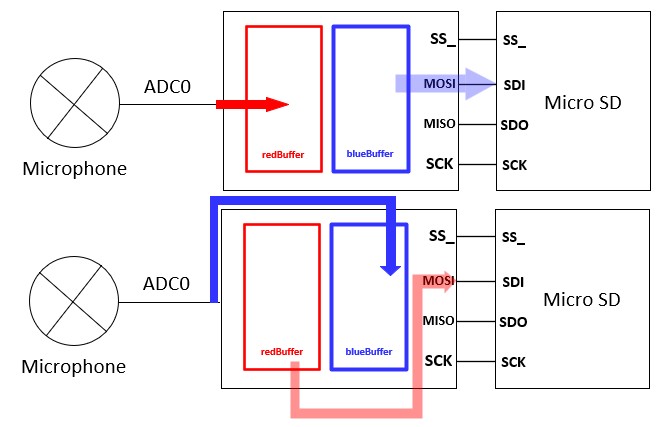
Task 2: Write blocks to and read blocks from the SD card. (30 points)
Task 3: Continuous data acquisition using the double buffering technique(40 points)
The
on-chip buffer is not large enough to store the analog input. To avoid
losing data, we use two buffers for continuous data acquisition. While
the redBuffer is not full, the ADC results are stored in the redBuffer,
handled by the ISR. The while loop in the loop() function writes data
to the SD card. This process can be interrupted by the data-acquisition
ISR, during which the other buffer will collect the input signal. Both
redBufferState and blueBufferState have two states: BEING_FILLED and
FILLED.
Here is the example code. You just need to fill out the buffer states with the "FILLED" state of the "BEING_FILLED" state. Demo video: