Part 2:
Creating TLV751
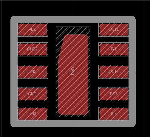
Figure 1: Footprint of TLB 751
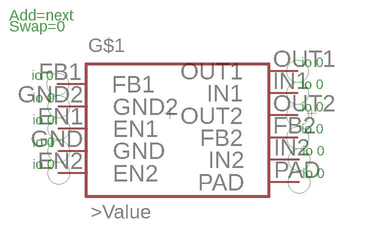
Figure 2: Connected device of TLV751
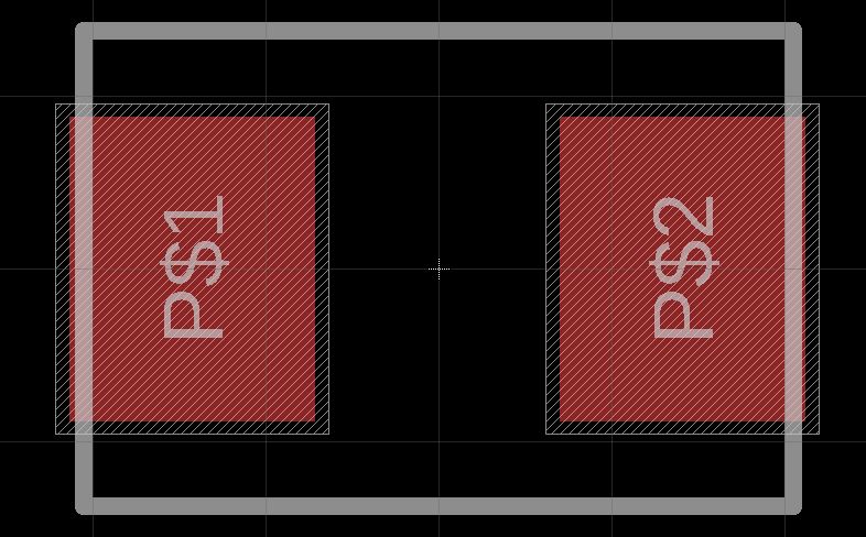
Figure 3: Footprint of 100uF Capasitor
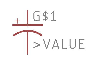
Figure 4: Connected device of 100uF Cap
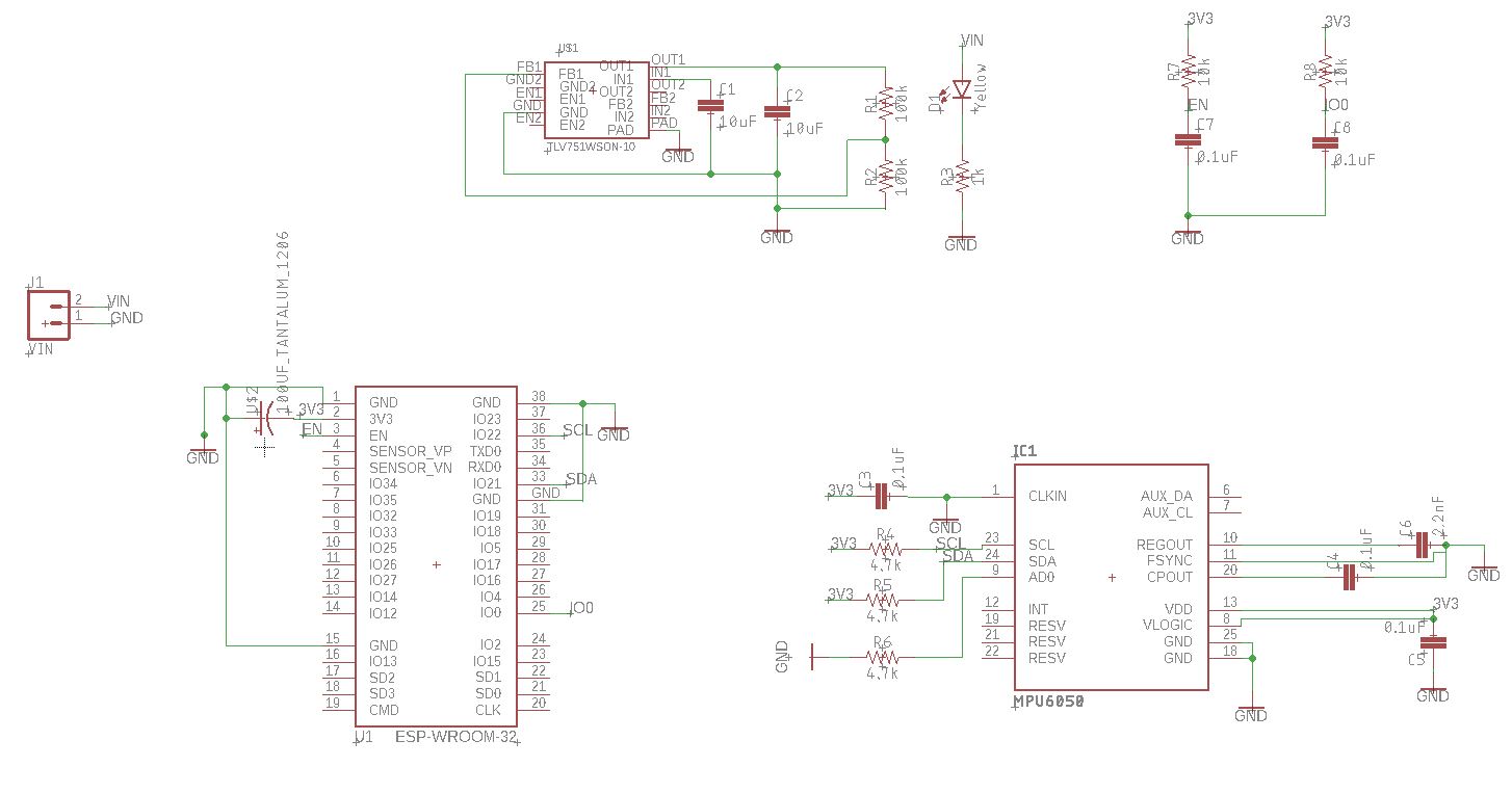
Figure 5: Schematic view of final board. Note that there were 2 ERC warnings and no errors and no DRC errors. I beleive that the ERC warnings could be ignored.
Figure 6: Board View with routing and no fill
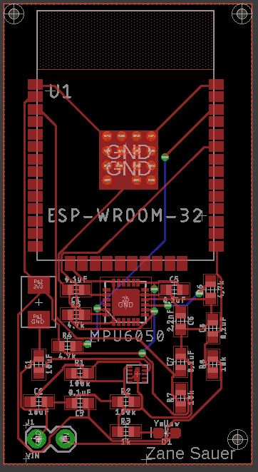
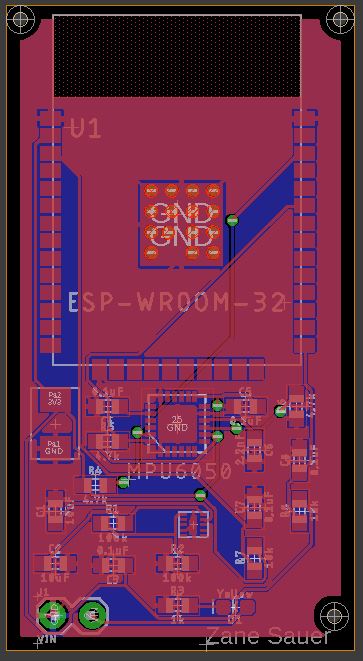
Figure 7: Board with ratsnest.
Gerber Files