Week 13-14
Project
ESP32
Introduction
For our final project we were given the
opportunity to either
fabricate the IoT Temperature Monitor that we designed in
Homework 2 or the ESP32 module that was designed in Homework 3.
I chose to fabricate the ESP32 module as I enjoyed learning and
designing the module in Homework 3. In order to creat the
module, we needed to design the module using EAGLE, have the PCB
fabricated through PCBWay, solder all the necessary parts to the
PCB board, and finally test the module.
Design
To
design the PCB needed to create the ESP32 module we needed to
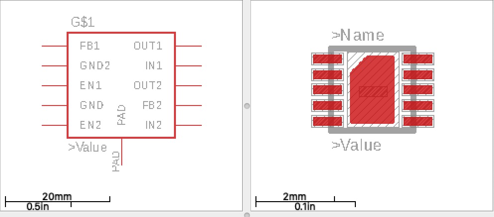
use EAGLE. The first thing we needed to do was to find the right
low-dropout (LDO) voltage regulator to use for our module. The
Texas Instrument TLV7510 voltage regulator was selected as it
best fit the specifications for our module. In EAGLE we needed
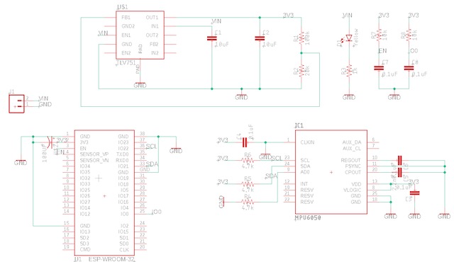
to create the TLV7510 component as shown in Figure 1. Once we
had all the required parts to design our module in EAGLE we
created a schematic to connect the components as shown in Figure
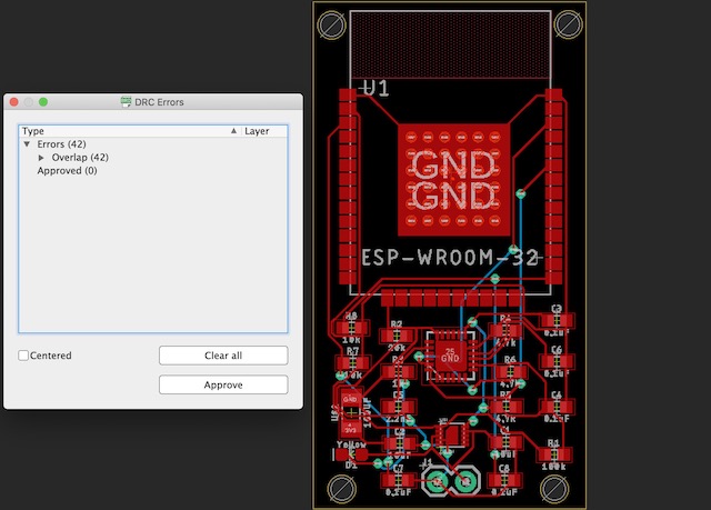
2. After the schematic was completed, the BRD layout could be
created where we could place the components on the PCB as
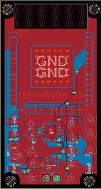
desired and route the PCB, which is shown in Figure 3. Then when
the board was routed we could finally pour the copper to finish
the board and we would have a finished product that would be
ready for fabrication as shown in Figure 4.
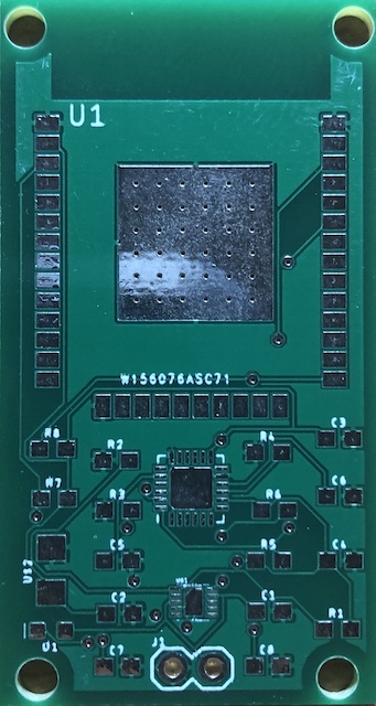
Fabrication
Once
we had the PCB created we created the gerber files that would be
sent to PCBWay so they could fabricate the board. Before sending
the gerber files, we needed to use an online PCB viewer like PCB
Investigator to check to make sure the board was designed
correctly as shown in Figure 5. Once we confirmed everything
looked correct we sent Dr. Li our gerber files so he could order
the PCB from PCBWay that way we can get a fabricated PCB like
the one shown in Figure 6.
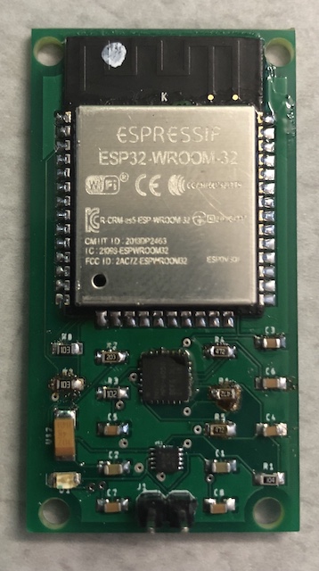
Solder
Testing
MASTER CODE:
#include "FS.h"
#include "SD.h"
#include "SPI.h"
#include<esp_now.h>
#include<WiFi.h>
#include<Wire.h>
const int MPU=0x68;//Device address
int16_t AccX, AccY, AccZ;
uint8_t broadcastAddress[] = {0x24, 0x62, 0xAB,
0xF9, 0x24, 0xC8}; // Receiver's mac address
typedef struct struct_message{
int16_t AccX, AccY, AccZ;
} struct_message;
struct_message MPU6050Readings;
void setup(){
Wire.begin(); //To redefine the
I2C pins: Wire.begin(SDA,SCL) or Wire.begin(SDA,
SCL, Bus_Speed).
Wire.beginTransmission(MPU);
Wire.write(0x6B);//Wake up the
MPU chip
Wire.write(0x00);
Wire.endTransmission(true);
Wire.beginTransmission(MPU);
Wire.write(0x1C);//Talk to the
ACCEL_CONFIG register (1C hex)
Wire.write(0x08);//Set the
register bits as 00001000 (+/- 4g full scale
range)
Wire.endTransmission(true);
Serial.begin(115200); // It's
fine to use a higher speed other than 9600 but
remember to change the rate in your serial monitor
WiFi.mode(WIFI_STA);
if (esp_now_init() != ESP_OK) {
Serial.println("Error initializing ESP-NOW");
return;
}
esp_now_peer_info_t peerInfo;
memcpy(peerInfo.peer_addr,
broadcastAddress, 6);
peerInfo.channel = 0;
peerInfo.encrypt = false;
if
(esp_now_add_peer(&peerInfo) != ESP_OK){
Serial.println("Failed to add peer");
return;
}
}
void loop(){
accRead();
MPU6050Readings.AccX=AccX;
MPU6050Readings.AccY=AccY;
MPU6050Readings.AccZ=AccZ;
esp_err_t result =
esp_now_send(broadcastAddress, (uint8_t *)
&MPU6050Readings, sizeof(MPU6050Readings));
//Send the data. &MPU6050Readings is just a
8-bit character pointer to store the data
}
void accRead(){ // read the MPU data to ESP32
Wire.beginTransmission(MPU);
Wire.write(0x3B);//Start with
register 0x3B
Wire.endTransmission(false);
Wire.requestFrom(MPU,6,true);//
Read 6 registers total
AccX=Wire.read()<<8 |
Wire.read();
AccY=Wire.read()<<8 |
Wire.read();
AccZ=Wire.read()<<8 |
Wire.read();
Wire.endTransmission(true);
}
SLAVE CODE:
#include "FS.h"
#include "SD.h"
#include "SPI.h"
#include<esp_now.h>
#include<WiFi.h>
#include<Wire.h>
int16_t incomingAccX, incomingAccY, incomingAccZ;
const int MPU=0x68;//Device address
typedef struct struct_message{
int16_t AccX, AccY, AccZ;
} struct_message;
struct_message incomingReadings;
void OnDataRecv(const uint8_t * mac, const uint8_t
*incomingData, int len) {
memcpy(&incomingReadings, incomingData,
sizeof(incomingReadings));
incomingAccX=incomingReadings.AccX;
incomingAccY=incomingReadings.AccY;
incomingAccZ=incomingReadings.AccZ;
}
void setup(){
Serial.begin(115200);
WiFi.mode(WIFI_STA);
if (esp_now_init() != ESP_OK) {
Serial.println("Error initializing ESP-NOW");
return;
}
esp_now_register_recv_cb(OnDataRecv);
}
void loop(){
Serial.print(incomingAccX);
Serial.print(" ");
Serial.print(incomingAccY);
Serial.print("
");
Serial.println(incomingAccZ);
}
Discussion