Week 8-11    Advanced IoT Devices (ESP 32)

Introduction

In this lecture, we learned about the ESP32 module, MPU6050 module, and Micro SD card adapter. The goal was to become more familiar with the ESP32 module. We used the I2C communication protocol extensively to communicate between module. We further refined our skills using EAGLE to create a PCB that incorporated the ESP32 and MPU6050 modules.


Task 1


For Task 1, we needed to install esp32 through the board manager. Once it was installed we had to configure it in Arduino by choosing the 'ESP32 Dev Module' board, the '11520 upload speed', the 'AVRISP mkII' programmer. After it was configured, we were given a simple blinking program to run and the results are shown in the video below.

Task 2


For Task 2, we were the connection layout for the ESP32 and MPU6050 and had to make the connections as shown in Figure 1. Once the MPU6050 was connected to the ESP32 we were given some code to run that would acquire data from the MPU and plot the data in the Serial Plotter as shown in the video below.


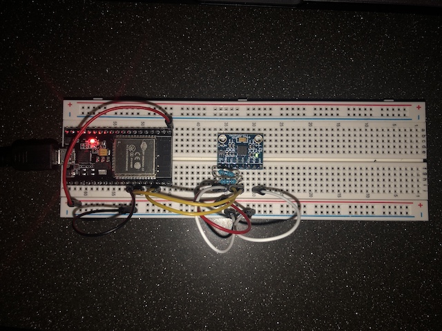
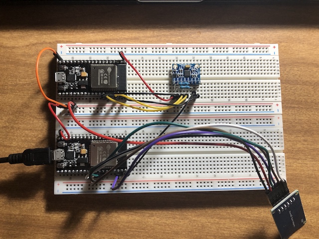
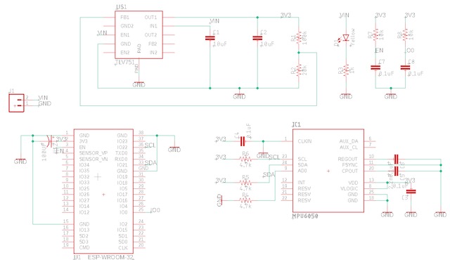
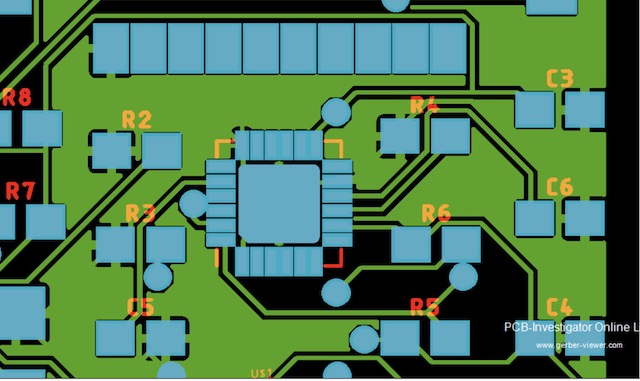
Figure 1. Layout for connecting MPU6050 to ESP32.


Task 3

For Task 3, we were presented with a variation of different codes that had flaws in them that would produce the incorrect plot. The fifth piece of code that was presented gave us the correct plot as can be seen in the video below.

Task 4

For Task 4, we added a micro SD card adapter so that we could store the data collected on an SD card, as shown in 
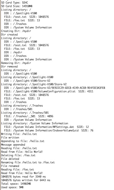
Figure 2. We were given some code that let us know that our SD card was communicating with your ESP board successfully. The result of the SD card communicating with the ESP board can be seen below in Figure 3.

Figure 2. ESP and SD card being connected together.


Figure 3. Output from ESP and SD card being connected together.

Task 5

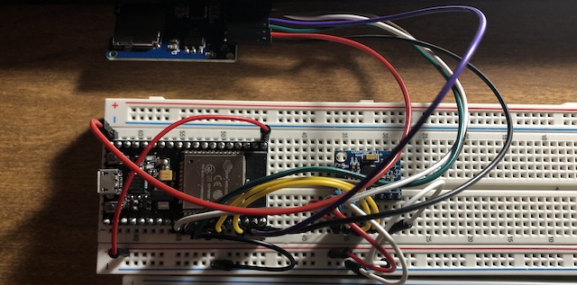
For Task 5, we connected the ESP, MPU, and SD card together so that the data read from the MPU could be stored on the SD 
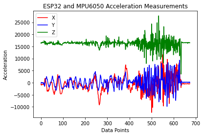
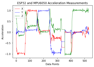
card, the setup is shown in Figure 4. We then had to modify the code given to receive all AccX, AccY, and AccZ data in separate data files 'AccX.txt', 'AccY.txt', and 'AccZ.txt' and then 
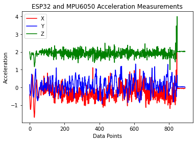
plot the data using python as shown in Figure 5.


Figure 4. ESP, MPU, and SD card being connected together.


Figure 5. Plotted data from SD card.

Task 6

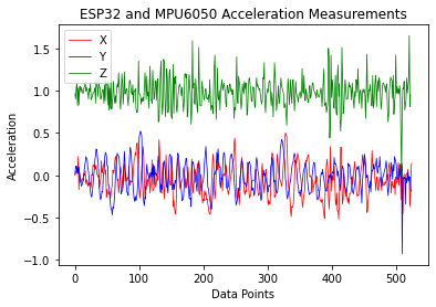
For Task 6, we had to change the data type of AccX, AccY, and AccZ to 'float' and use the intermediate int16_t variables AccX_temp, AccY_temp, and AccZ_temp to store the 16-bit accelleration data from the MPU sensor. Then we used python to plot the data acquired as shown in Figure 6.


Figure 6. Plotted data from SD card.

Task 7

For Task 7, we connected two ESP module together, as shown in Figure 7, 
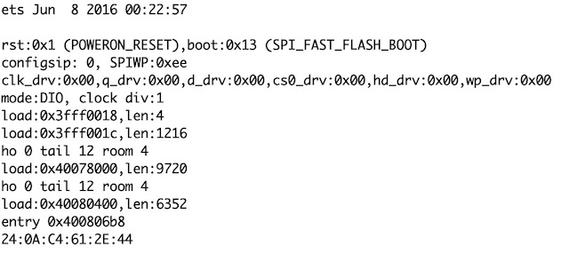
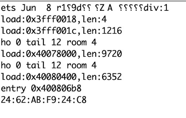
but we need to get the MAC address of each module, which can be seen in Figure 8 and Figure 9.  We were given code that needed to be uploaded to the master and the slave respectively, then connect the USB cable to the slave. Once the code had been uploaded to both ESPs then we could open the serial plotter in Arduino and it would show the data being plotted in realtime as shown in the video below.


Figure 7. Connecting two ESP modules and MPU6050.


Figure 8. Master MAC address.


Figure 9. Slave MAC address.


Task 8

For Task 8, we needed to add the SD card so that we could store the data the was transferred from the master to the slave from the MPU. The setup is shown in the Figure 10. Then we had

to alter the code given to receive the acceleration data from the master wirelessly by the slave and store the data to the SD card. After we plotted the stored data using python as shown in

Figure 11 and Figure 12.


Figure 10. Connection of ESPs, MPU, and SD card.


Figure 11. Testing the MPU in the x, y, and z axis.


Figure 12. Plotted data from SD card.

Task 9

For Task 9, we needed to clean up the code for the master and slave, which are both given below. Then we used the cleaned up code to acquire data to store on the SD card and used python to plot the data as shown in Figure 13.

// Task 9 MASTER
#include "FS.h"
#include "SD.h"
#include "SPI.h"
#include<esp_now.h>
#include<WiFi.h>
#include<Wire.h>
const int MPU=0x68;//Device address
int16_t AccX, AccY, AccZ;
uint8_t broadcastAddress[] = {0x24, 0x62, 0xAB, 0xF9, 0x24, 0xC8}; // Receiver's mac address

typedef struct struct_message{
    int16_t AccX, AccY, AccZ;
} struct_message;

struct_message MPU6050Readings;

void setup(){
    Wire.begin(); //To redefine the I2C pins: Wire.begin(SDA,SCL) or Wire.begin(SDA, SCL, Bus_Speed).
    Wire.beginTransmission(MPU);
    Wire.write(0x6B);//Wake up the MPU chip
    Wire.write(0x00);
    Wire.endTransmission(true);
    Wire.beginTransmission(MPU);
    Wire.write(0x1C);//Talk to the ACCEL_CONFIG register (1C hex)
    Wire.write(0x08);//Set the register bits as 00001000 (+/- 4g full scale range)
    Wire.endTransmission(true);     
    Serial.begin(115200); // It's fine to use a higher speed other than 9600 but remember to change the rate in your serial monitor
    WiFi.mode(WIFI_STA);
    if (esp_now_init() != ESP_OK) {
      Serial.println("Error initializing ESP-NOW");
      return;
    }
    esp_now_peer_info_t peerInfo;
    memcpy(peerInfo.peer_addr, broadcastAddress, 6);
    peerInfo.channel = 0;
    peerInfo.encrypt = false;
    if (esp_now_add_peer(&peerInfo) != ESP_OK){
      Serial.println("Failed to add peer");
      return;
  }
}
void loop(){
    accRead();
    MPU6050Readings.AccX=AccX;
    MPU6050Readings.AccY=AccY;
    MPU6050Readings.AccZ=AccZ;
    esp_err_t result = esp_now_send(broadcastAddress, (uint8_t *) &MPU6050Readings, sizeof(MPU6050Readings)); //Send the data. &MPU6050Readings is just a 8-bit character pointer to store the data
}
void accRead(){ // read the MPU data to ESP32
    Wire.beginTransmission(MPU);
    Wire.write(0x3B);//Start with register 0x3B
    Wire.endTransmission(false);
    Wire.requestFrom(MPU,6,true);// Read 6 registers total
    AccX=Wire.read()<<8 | Wire.read();
    AccY=Wire.read()<<8 | Wire.read();
    AccZ=Wire.read()<<8 | Wire.read();
    Wire.endTransmission(true);
}


//Task 9 SLAVE
#include "FS.h"
#include "SD.h"
#include "SPI.h"
#include<esp_now.h>
#include<WiFi.h>
#include<Wire.h>
int16_t incomingAccX, incomingAccY, incomingAccZ;
const int MPU=0x68;//Device address

typedef struct struct_message{
  int16_t AccX, AccY, AccZ;
} struct_message;

struct_message incomingReadings;

void OnDataRecv(const uint8_t * mac, const uint8_t *incomingData, int len) {
  memcpy(&incomingReadings, incomingData, sizeof(incomingReadings));
  incomingAccX=incomingReadings.AccX;
  incomingAccY=incomingReadings.AccY;
  incomingAccZ=incomingReadings.AccZ;
}
void setup(){
    Serial.begin(115200);
    WiFi.mode(WIFI_STA);
    if (esp_now_init() != ESP_OK) {
      Serial.println("Error initializing ESP-NOW");
      return;
    }
    Wire.begin(); //To redefine the I2C pins: Wire.begin(SDA,SCL) or Wire.begin(SDA, SCL, Bus_Speed).
    Wire.beginTransmission(MPU);
    Wire.write(0x6B);//Talk to the ACCEL_CONFIG register (1C hex)
    Wire.write(0x0);
    Wire.endTransmission(true);
    Serial.begin(115200);
        if(!SD.begin()){
        Serial.println("Card Mount Failed");
        return;
    }
    esp_now_register_recv_cb(OnDataRecv);
}
void loop(){
  uint8_t cardType = SD.cardType();
    if(cardType == CARD_NONE){
        Serial.println("No SD card attached");
        return;
    }
    appendFileAndChar(SD, "/AccX.txt", incomingAccX, ",");
    appendFileAndChar(SD, "/AccY.txt", incomingAccY, ",");
    appendFileAndChar(SD, "/AccZ.txt", incomingAccZ, ",");
}
void appendFileAndChar(fs::FS &fs, const char * path, int16_t message, const char * seperate){ // changed the argument type to int16_t

    File file = fs.open(path, FILE_APPEND);
    if(!file){
        Serial.println("Failed to open file for appending");
        return;
    }
    if(file.print(message){
        file.print(seperate);
        Serial.println("Message appended");
    } else {
        Serial.println("Append failed");
    }
    file.close();
}


Figure 13. Plotted data from SD card.


PART 2 ESP32, MPU6050 Interfaces and the PCB Design


Figure 14. Created TLV751 Voltage Regulator.


Figure 15. Schematic of module.


Figure 16. Routed PCB with errors due to the vias.


Figure 17. Finished PCB.


Figure 18. Checking PCB using PCB Investigator.


Figure 19. Closer look of PCB to make sure metal pads are not covered with solder mask.


Discussion

By completing these tasks it gave me a better understanding of the ESP32 module, MPU6050 module, and the I2C communication protocol. I was able to refine my programming skills by seeing different ways that code could be implemented. I was also to get more experience with EAGLE as we created a module that used the ESP32 and MPU6050 modules, which Dr. Li is sending to PCBWay to get fabricated as that will be our final project. This was a good hands on learning experience.