ENGR 338 2021 Spring
Lab 8: Design a MUX and a High-Speed Full Adder
Taylor Nakai
tsnakai@fortlewis.edu
Introduction:
In
this lab, we used ElectriVLSI to build an 8-bit MUX, build a 1-bit
high-speed full adder, and build an 8-bit high-speed full adder. For
the 8-bit
MUX, 1-bit high-speed full adder, and 8-bit high-speed full adder we
had to create a schematic, icon, layout, and perform simulations using
LTSpice to verify the functionality of the logic.
Task 1:
In
task 1, we were given the task of building an 8-bit MUX, but in order
to do this a 2-1 MUX needed to be created first. To begin, a 2-1 MUX
schematic and icon was created as shown in Figure 1. To make sure that
the 2-1 MUX was correctly implemented, we needed to perform a
simulation to verify the logic as shown in Figure 2. Once that was
completed we moved on to build the layout of the 2-1 MUX shown in
Figure 3. Since we had 2-1 MUX built, it was easy to implement a 8-bit
2-1 MUX using buses. We created the schematic of the 8-bit 2-1 MUX as
shown in Figure 4. To check the logic of the 8-bit 2-1 MUX a simulation
was performed as shown in Figure 5. Finally the layout of the 8-bit 2-1
MUX could be implemented using the 2-1 MUX layout shown in Figure 6.
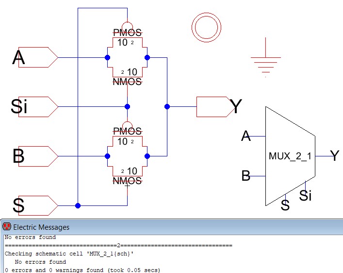
Figure 1. Schematic and icon of 2-1 MUX and clean DRC.
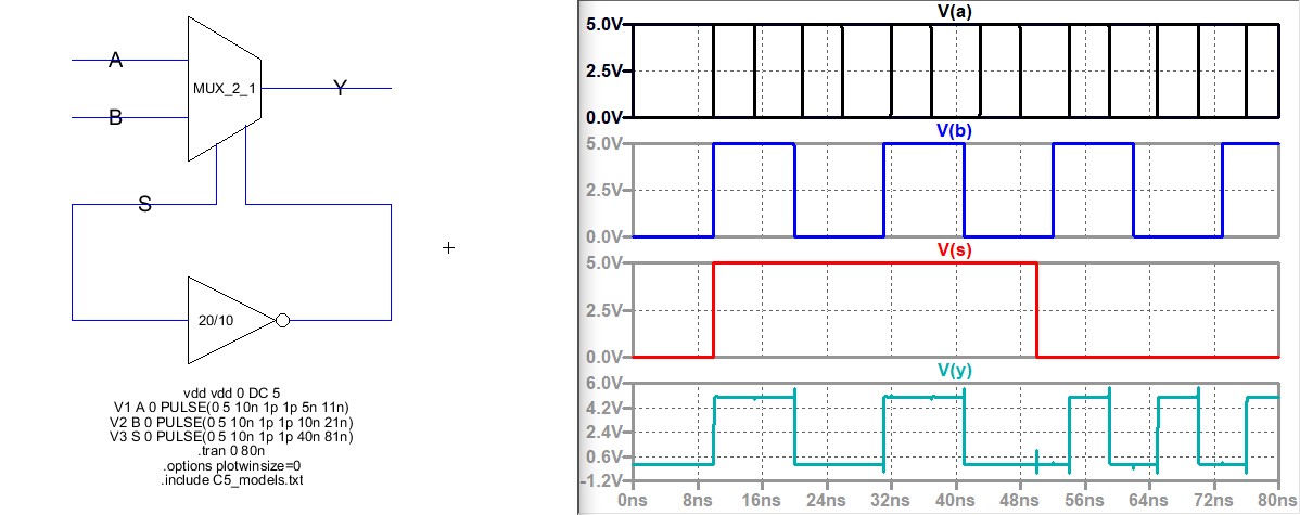
Figure 2. Simulation using LTSpice to verify the logic of the 2-1 MUX.
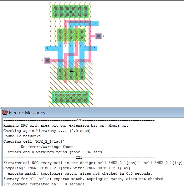
Figure 3. Layout of 2-1 MUX with a clean DRC and NCC.
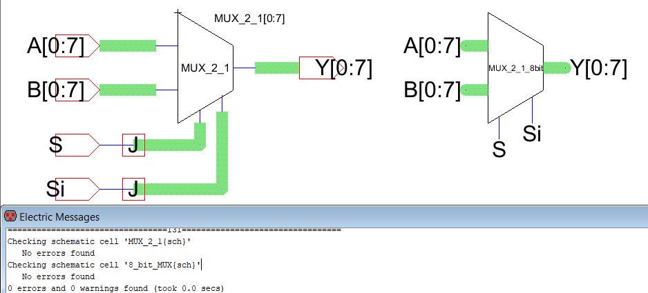
Figure 4. Schematic and icon of 8-bit 2-1 MUX with clean DRC.
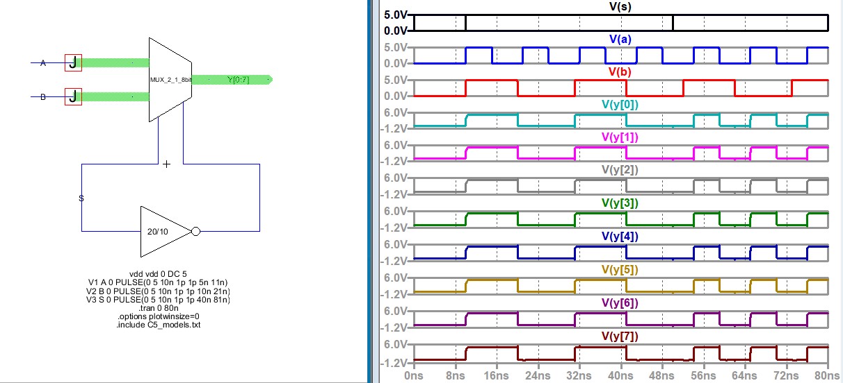
Figure 5. Simulation using LTSpice to verify the logic of the 8-bit 2-1 MUX.
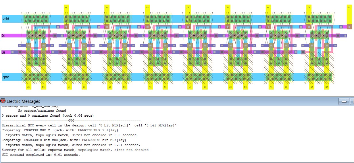
Figure 6. Layout of 8-bit 2-1 MUX with a clean DRC and NCC.
Task 2:
In task 2, we were given the task of building
a 1-bit high-speed full adder. In order to do so, we needed to follow
the AOI logic implementation in Dr. Baker's CMOS book. By following the
implementation we were able to create the schematic as shown in Figure
7. We need to check the implementation of the 1-bit
high-speed full adder to verify the logic, so we ran a simulation as
seen in Figure 8. Once the verification of the logic was complete, we
were able to build the layout of the 1-bit high-speed full adder as shown in Figure 9.
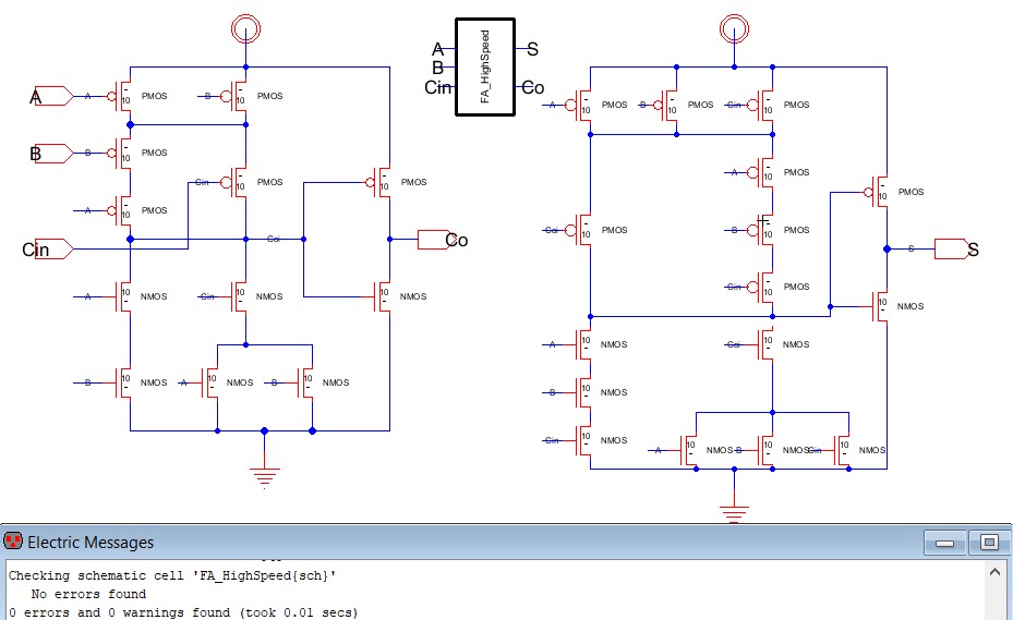
Figure 7. Schematic and icon of a 1-bit high-speed full adder with clean DRC.
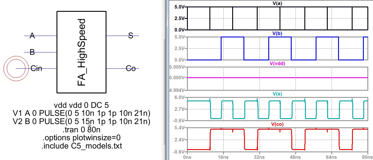
Figure 8. Simulation using LTSpice to verify the logic of the 1-bit high-speed full adder.
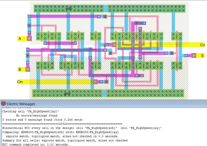
Figure 9. Layout of 1-bit high-speed full adder with a clean DRC and NCC.
Task 3:
In
task 3, we were given the task of building an 8-bit high-speed full
adder. Using the 1-bit high-speed full-adder we were able implement an
8-bit high-speed full-adder schematic using buses as shown in Figure
10. We needed to check the implementation of the 8-bit
high-speed full adder to verify the logic, so we ran a simulation as
seen in Figure 11 - 14. Once the logic was verified, we were able to
create the layout for the 8-bit high-speed full-adder as seen in Figure
15.
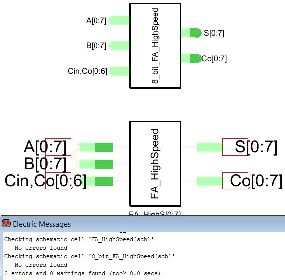
Figure 10. Schematic and icon of a 8-bit high-speed full adder with clean DRC.
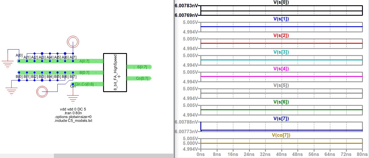
Figure 11. Simulation using LTSpice to verify the logic of the 8-bit high-speed full adder. 11111110 + 10000000 = 01111110, Co = 1.
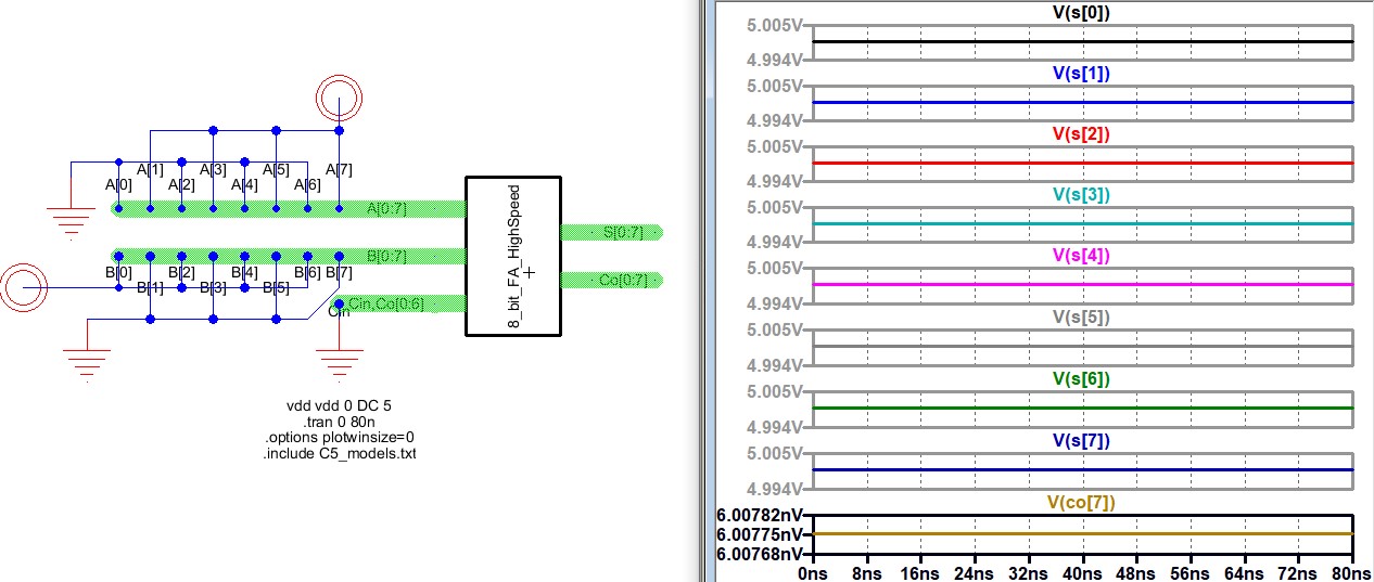
Figure 12. Simulation using LTSpice to verify the logic of the 8-bit high-speed full adder. 10101010 + 01010101 = 11111111, Co = 0.
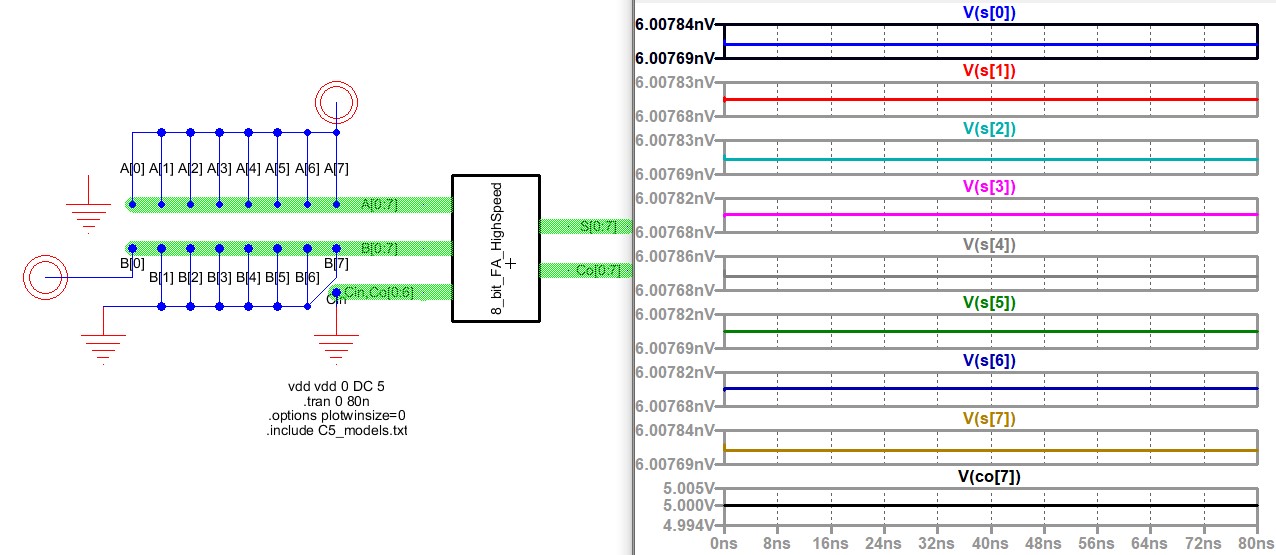
Figure 13. Simulation using LTSpice to verify the logic of the 8-bit high-speed full adder. 11111111 + 00000001 = 00000000, Co = 1.
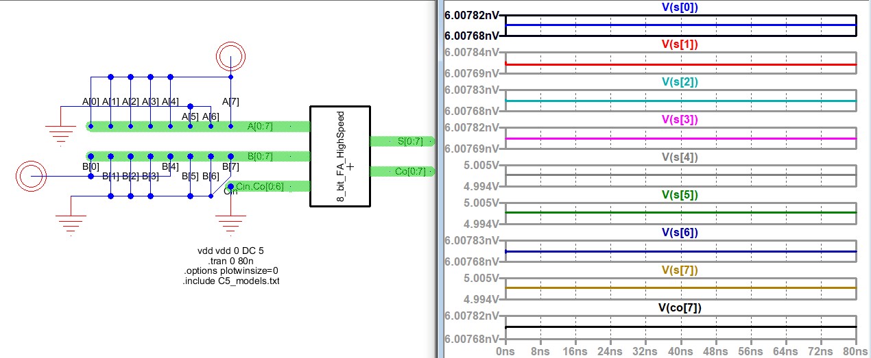
Figure 14. Simulation using LTSpice to verify the logic of the 8-bit high-speed full adder. 10011111 + 00010001 = 10110000, Co = 0.
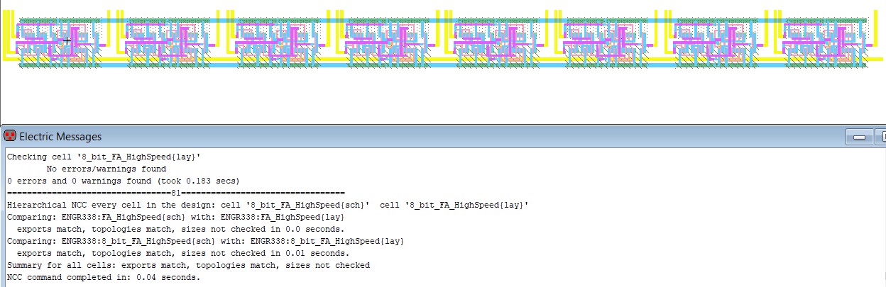
Figure 15. Layout of 8-bit high-speed full adder with a clean DRC and NCC
Discussion:
By
completing this lab, we were able to gain more experience with
ElectriVLSI, create the schematic and layout of an 8-MUX, and create
the schematic and layout of an 8-bit high-speed full-adder. I was
successfully able to complete all the tasks required using ElectriVLSI
and LTSpice. I think that the creating the layouts in this lab took a
lot of patience as there were many connections that needed to be made.
Hopefully, this will prepare me for the last lab, which looks like it
will take forever with all the connections in the layout.