CE 433 Spring 2022 Lab 2: Verilog, Vivado, and FPGA Basics Taylor Nakai tsnakai@fortlewis.edu
Introduction: In
this lab, we were tasked with gaining comfortability working with
verilog, vivado, and FPGA. This lab allowed me to become comfortable in
creating a new project, selecting the proper chipset for a FPGA, create
and add design sources, creating testbenches, running simulations, and
performing on-board verifications. We were tasked with following the
tutorial to code, simulate, and on-board verify different digital
gates, such as the AND, OR, and XOR. We also were able to learn about
the volatile and nonvolatile ways of programming an FPGA.
Task 1: AND Gate In
this task, we were tasked with going through the tutorial to code,
simulate, on-board verify an AND gate. To begin we created two design
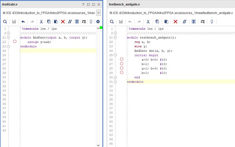
sources, as seen in Figure 1, with the AND gate being designed using
the dataflow modeling method on the left and the testbench to verify
the logic of the digital gate on the right. Once that was completed, we
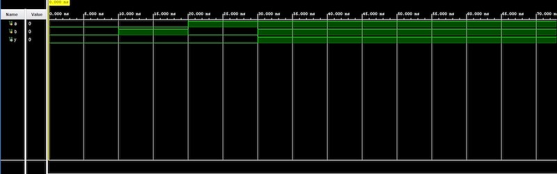
were able to run a behavioral simulation to ensure that the logic
follows the truth table of the digital gate as shown in Figure 2. To be
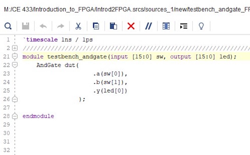
able to verify the logic on the FPGA, we needed to import a contraiint
file to define the pins in the FPGA. After we were able to create a
testbench that would be used to verify the logic on the FPGA shown in
Figure 3. The .bit and .bin files were created so that we could use
either the volatile or nonvolatile methods to program our FPGA, which
the on-board verification are shown in Figure 4 and 5.
Figure 1. Module and testbench code associated with an AND gate.
Figure 2. Vivado simulation of AND gate verifying that it is implementing the correct logic.
Figure 3. Testbench code to verify logic on FPGA.
Figure 4. Demonstration showing on-board verification of AND gate using volatile method.
Figure 5. Demonstration showing on-board verification of AND gate using nonvolatile method.
Task 2: In
this task, we were tasked with going through the tutorial to code,
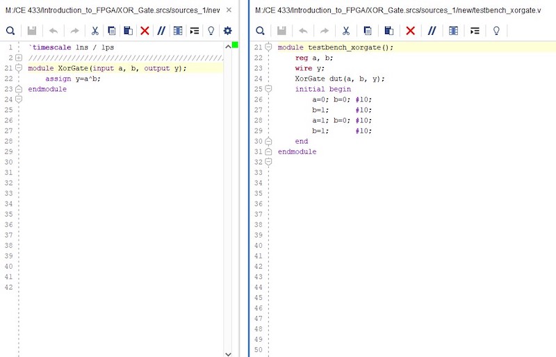
simulate, on-board verify an OR and XOR gate. To begin we created two design
sources, as seen in Figures 6 and 11, with the digital gates were designed using
the dataflow modeling method on the left and the testbench to verify
the logic of the digital gate on the right. Once that was completed, we
were able to run a behavioral simulation to ensure that the logic
follows the truth table of the digital gates as shown in Figures 7 and 12. To be
able to verify the logic on the FPGA, we needed to import a contraiint
file to define the pins in the FPGA. After we were able to create a
testbench that would be used to verify the logic on the FPGA shown in
Figures 8 and 13. The .bit and .bin files were created so that we could use
either the volatile or nonvolatile methods to program our FPGA, which
the on-board verification are shown in Figures 9-10 and 14-15.
XOR GATE Figure 6. Module and testbench code associated with an XOR gate.
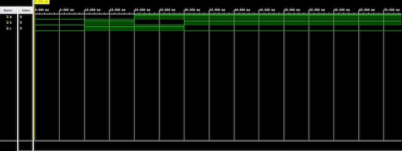
Figure 7. Vivado simulation of XOR gate verifying that it is implementing the correct logic.
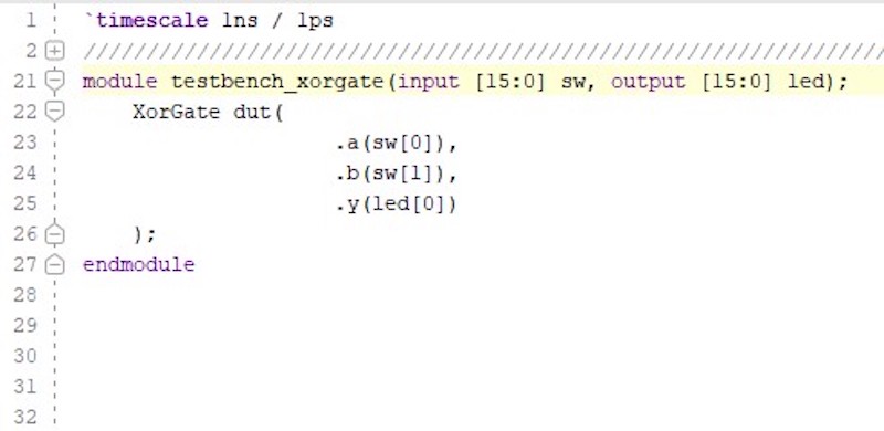
Figure 8. Testbench code to verify logic on FPGA.
Figure 9. Demonstration showing on-board verification of XOR gate using volatile method.
Figure 10. Demonstration showing on-board verification of XOR gate using nonvolatile method.
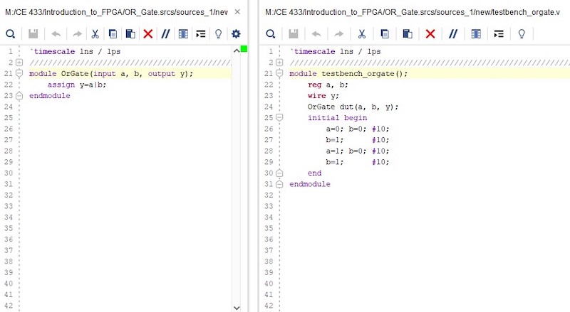
OR GATE Figure 11. Module and testbench code associated with an OR gate.
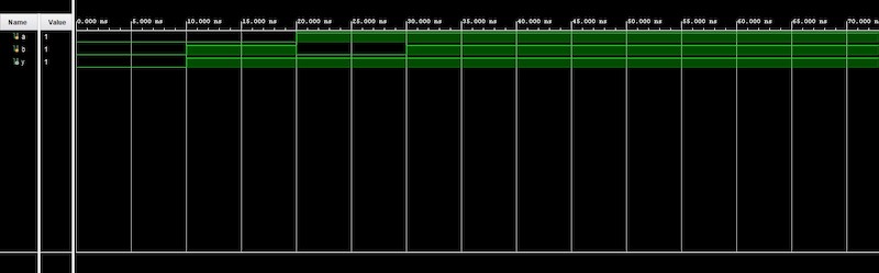
Figure 12. Vivado simulation of OR gate verifying that it is implementing the correct logic.
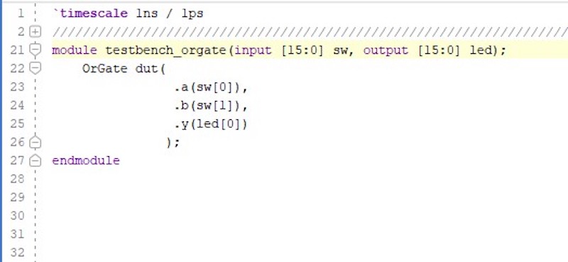
Figure 13. Testbench code to verify logic on FPGA.
Figure 14. Demonstration showing on-board verification of OR gate using volatile method.
Figure 15. Demonstration showing on-board verification of OR gate using nonvolatile method.
Discussion: By completing this lab, we were able
to gain comfortability working with verilog, vivado, and FPGA. Gaining
more experience creating design files and running behavioral
simulations would help me in future homework and labs. Learning about
.bin and .bit files and how they are used when using volatile and
nonvolatile methods was very interesting. I believe that these
techniques used in this lab are very beneficial. This was a good lab
where I was able to expand my knowledge. Overall, this lab was
interesting and I hope that we are able to build from this. ........................................................................................................