CE 433 Spring 2022 softCore Tutorial Taylor Nakai tsnakai@fortlewis.edu
Introduction: In
this homework, we were given the task of work with the workflow of SoC
design using KCPSM6 and the Basys 3 board to use the switches to turn
on/off the corresponding leds, implementing the square problem, adding
a 0x13 to the leds, implementing the use of MASK, shift the switch
input to the right by one bit, using a combination of jump, return, and
load instructions, practice implementing multiple subroutines, using
the 'compare' instruction instead of the 'test' instruction, and
implementing a design to show the number of switches that are ON on the
leds in binary notation.
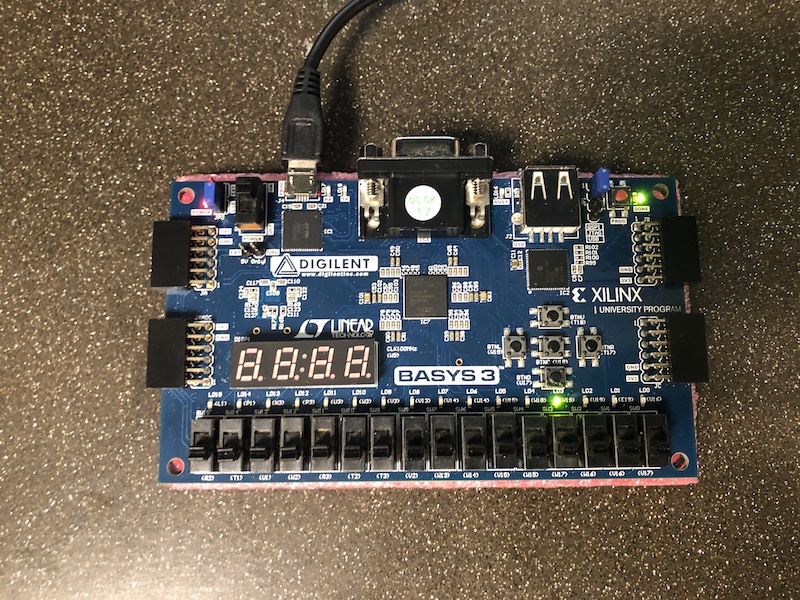
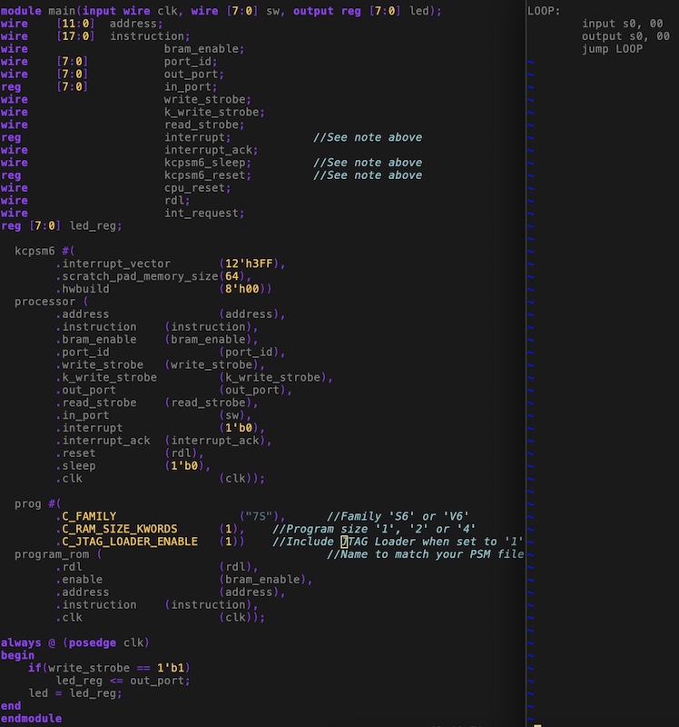
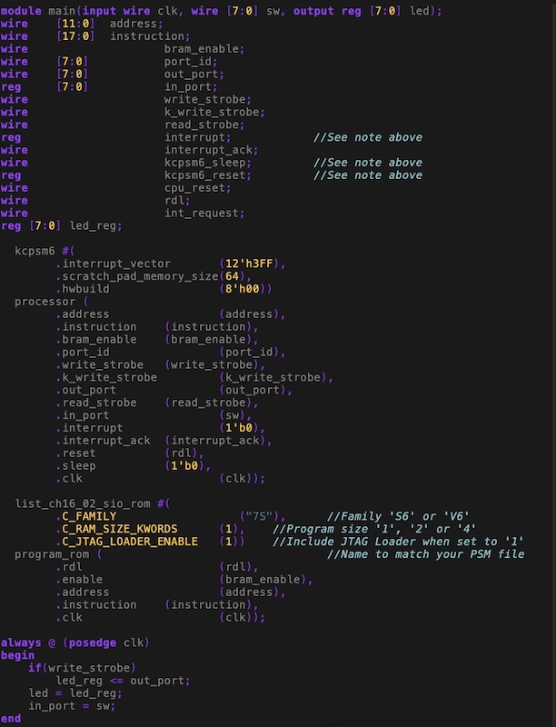
Task 3: In task 3, we were given the taskto use the switches to turn on/off the corresponding leds. Figure 1 shows the code used to implementusing the switches to turn on/off the corresponding leds. Figure 2 shows the demonstration using the switches to turn on/off the corresponding leds. Figure 1. Code used to implement using the switches to turn on/off the corresponding leds.
Figure 2. Demonstration of the implementation of using the switches to turn on/off the corresponding leds. Task 4: In task 4, we were given the taskto implement the square problem. Figure 3 shows the code used to implement the square problem. Figure 4 shows the demonstration implement the square problem. Figure 3. Code used to implementthe square problem.
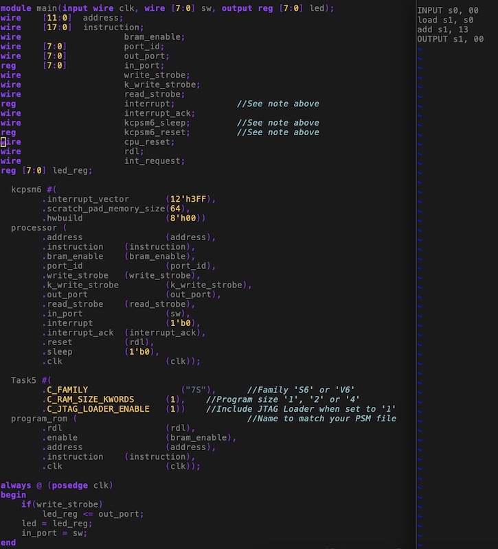
Figure 4. Demonstration of the square problem. Task 5: In task 5,we were given the taskto adding a 0x13 to the leds. Figure 5 shows the code used to implementadding a 0x13 to the leds. Figure 6shows the demonstrationadding a 0x13 to the leds.
Figure 5. Code used to implementadding a 0x13 to the leds.
Figure 6.Demonstration of theadding a 0x13 to the leds.
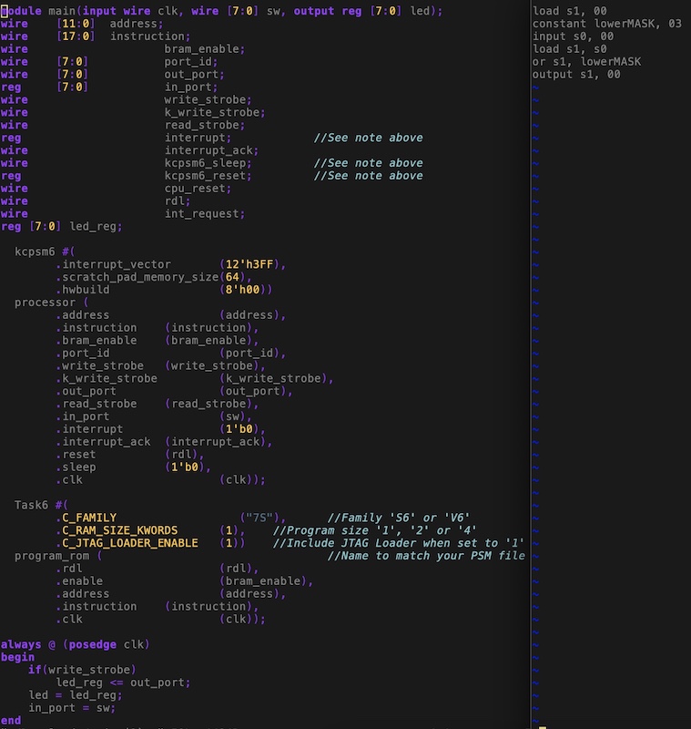
Task 6: In task 6,we were given the taskto implement the use of MASK so that the first two leds remain on. Figure 7 shows the code used to implement the use of MASK so that the first two leds remain on. Figure 8shows the demonstrationimplementing the use of MASK so that the first two leds remain on. Figure 7. Code used to implement the use of MASK.
Figure 8.Demonstration ofimplementation ofthe use of MASK.
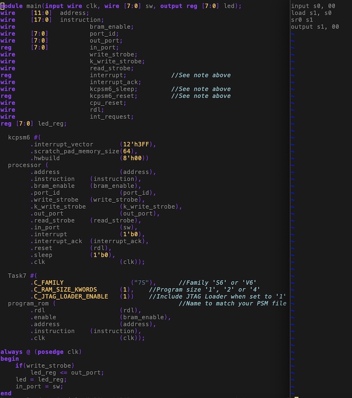
Task 7: In task 7,we were given the taskto use the shift the switch input to the right by one bit. Figure 9 shows the code used to implementusing the shift the switch input to the right by one bit. Figure 10shows the demonstrationusing the shift the switch input to the right by one bit. Figure 9. Code used to implementshifting the switch input to the right by one bit.
Figure 10.Demonstration ofshifting the switch input to the right by one bit.
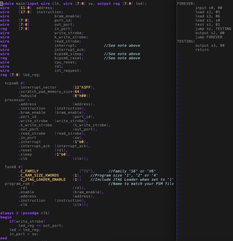
Task 8: In task 8,we were given the taskto use a combination of jump, return, and load instructions. Figure 11 shows the code used to implementusing a combination of jump, return, and load instructions. Figure 12shows the demonstrationusing a combination of jump, return, and load instructions. Figure 11. Code used to implementing a combination of jump, return, and load instructions.
Figure 12.Demonstration of thecombination of jump, return, and load instructions.
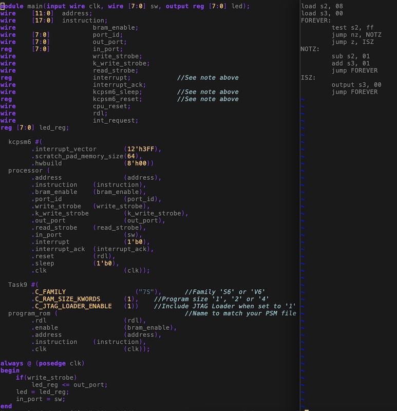
Task 9: In task 9,we were given the taskto practice implementing multiple subroutines. Figure 13 shows the code used to implementpracticing implementing multiple subroutines. Figure 14shows the demonstrationpracticing implementing multiple subroutines. Figure 13. Code used to implement thepractice of implementing multiple subroutines. Figure 14. Demonstration of thepractice of implementing multiple subroutines.
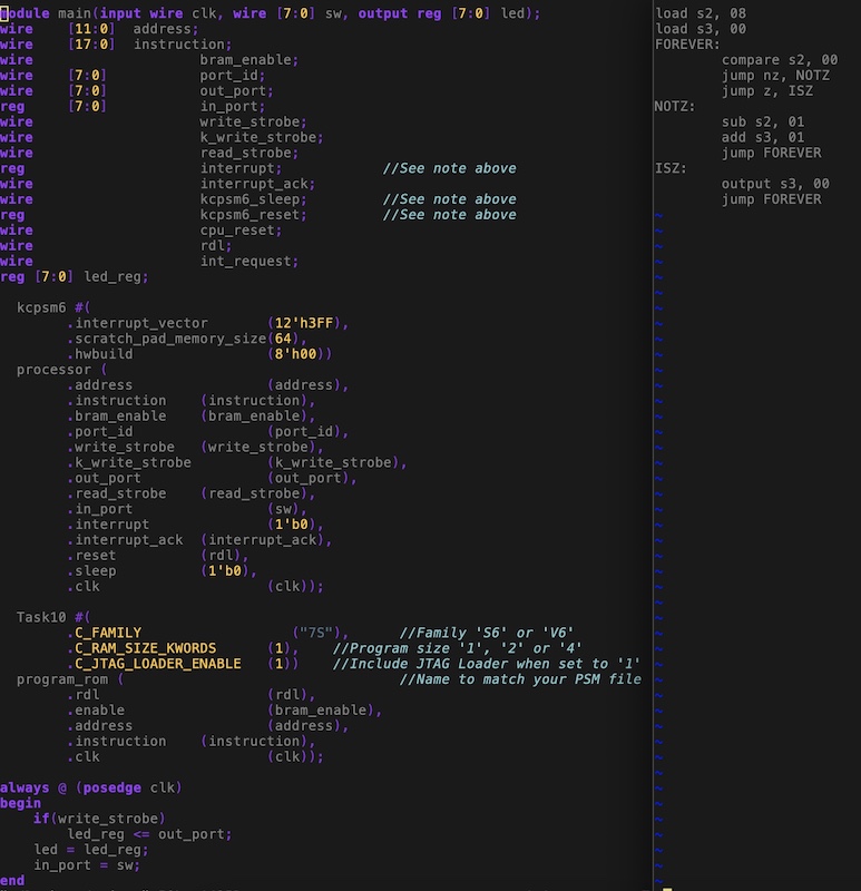
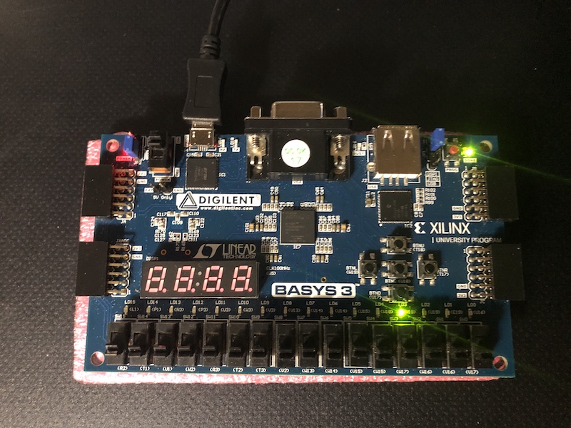
Task 10: In task 10,we were given the taskto use the 'compare' instruction instead of the 'test' instruction. Figure 15 shows the code used to implementusing the 'compare' instruction instead of the 'test' instruction. Figure 16shows the demonstrationusing the 'compare' instruction instead of the 'test' instruction. Figure 15. Code used to implementusing the 'compare' instruction instead of the 'test' instruction. Figure 16.Demonstration of using the 'compare' instruction instead of the 'test' instruction.
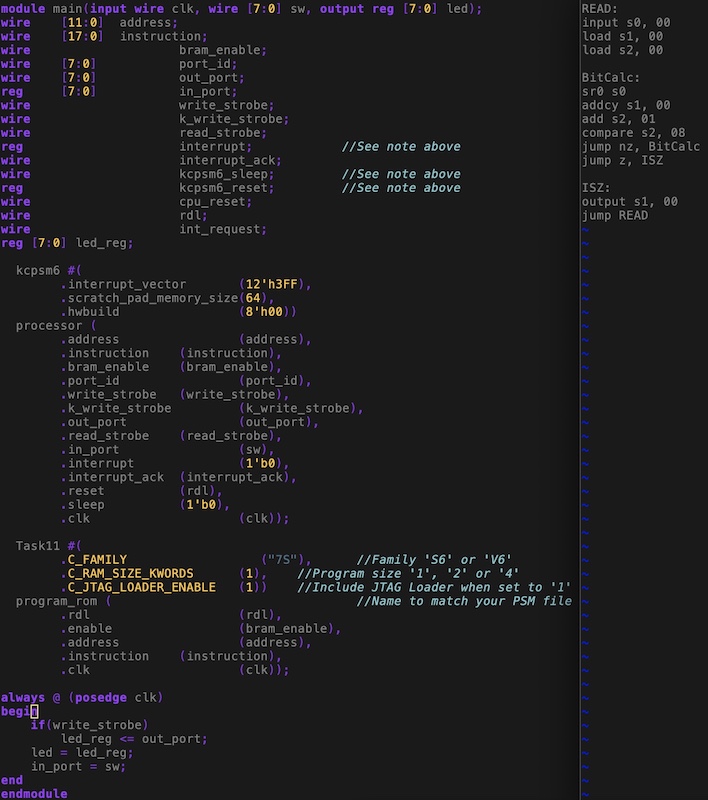
Task 11: In task 11,we were given the taskto implement a design to show the number of switches that are ON on the leds in binary notation. Figure 17 shows the code used to implement a design to show the number of switches that are ON on the leds in binary notation. Figure 18shows the demonstrationimplementing a design to show the number of switches that are ON on the leds in binary notation.
Figure 17. Code used to implementing a design to show the number of switches that are ON on the leds in binary notation.
Figure 18. Demonstration of implementing a design to show the number of switches that are ON on the leds in binary notation.
Discussion: By completing this homwork,it
allowed me to become more comfortable using the soft core PicoBlaze
basics. I really enjoyed working with the PicoBlaze softcore as it was
really interesting and beneficial learning the basics. I really liked this tutorial as it was something that I never have explored.Overall, I could see the use for this in industry and hope that I will be able to learn more. I look forward to the next! ...................................................................................................