CE 433 Spring 2022
Data Storage Tutorial
Taylor Nakai
tsnakai@fortlewis.edu
Introduction:
In
this homework, we were given the tasks of implementing SR Latches, SR
Flip Flops, D Latches, D Flip-Flops, JK Flip-Flops, T Flip-Flops, and
Read Only Memory (ROM) in verilog and simulating in vivado. This was a
great introduction into data storage units.
Task 1:
In task 1, we were given the task of implementing SR
Latches, SR Flip Flops, D Latches, D Flip-Flops in verilog and
simulating in vivado. Once the module and testbench were completed we
were able to run a behavioral simulation to verify the logic. Figure 1
shows the code and simulation of the SR Latch. Figure 2 shows the code and simulation of the SR Flip Flop. Figure 3 shows the code and simulation of the D Latch. Figure 4 shows the code and simulation of the D Flip Flop.
SR Latch:
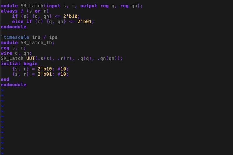
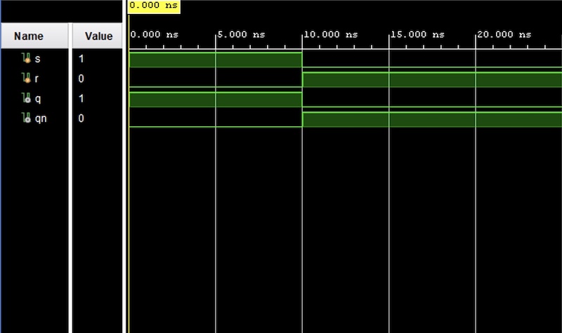
Figure 1. SR latch code implementation with vivado simulation.
SR Flip-Flop:
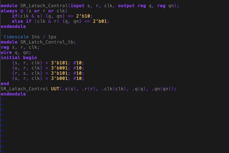
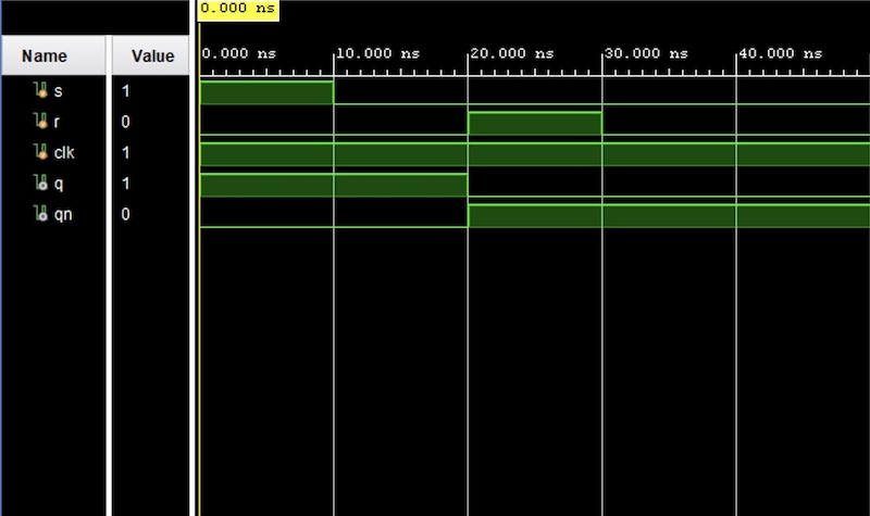
Figure 2. SR flip-flop code implementation with vivado simulation.
D Latch:
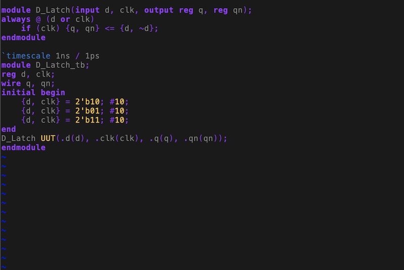
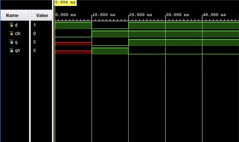
Figure 3. D latch code implementation with vivado simulation.
D Flip Flop:
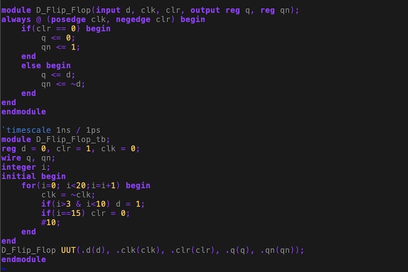
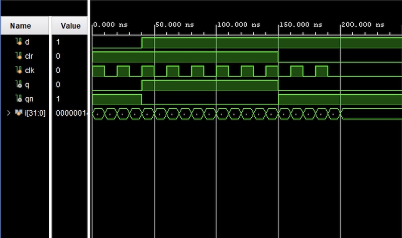
Figure 4. D flip-flop code implementation with vivado simulation.
Task 2:
In task 2, we were given the task of implementing edge triggered JK flip flop and T flip-flop in verilog and
simulating in vivado. Once the module and testbench were completed we
were able to run a behavioral simulation to verify the logic. Figure 5
shows the code and simulation of the edge triggered JK flip flop. Figure 6 shows the code and simulation of the T flip-flop.
JK Flip Flop:
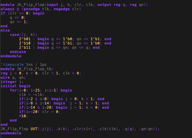
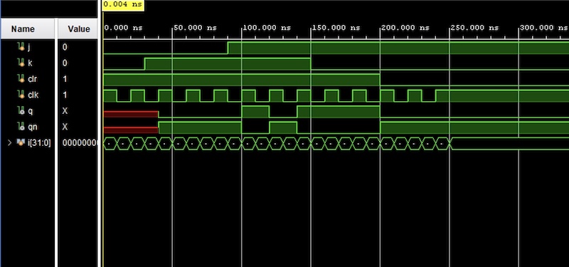
Figure 5. JK flip-flop code implementation with vivado simulation.
T Flip Flop:
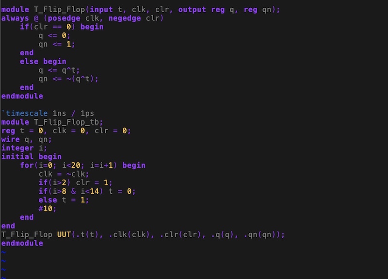
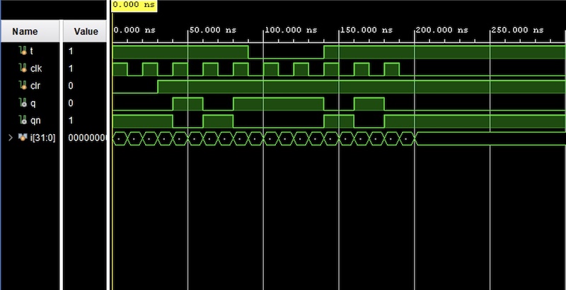
Figure 6. T flip-flop code implementation with vivado simulation.
Task 3:
In
task 3, we were tasked with constructing a rom memory in verilog. We
were able to read 8-bit binary numbers, 4 hex data, and 3-bit binary
numbers. Figure 7 shows the code and simulation of a rom memory using
8-bit numbers. Figure 8
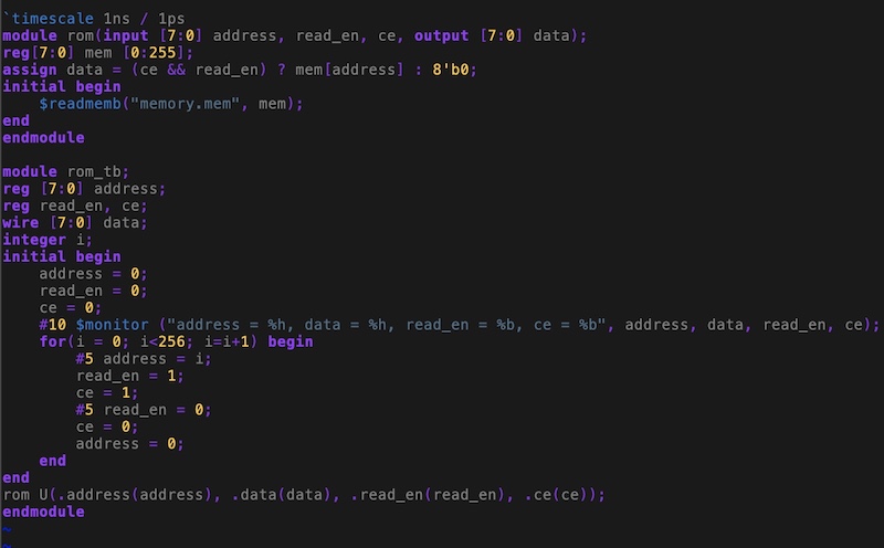
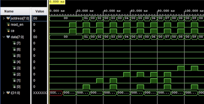
Figure 7. ROM memory using 8-bit binary code implementation with vivado simulation.
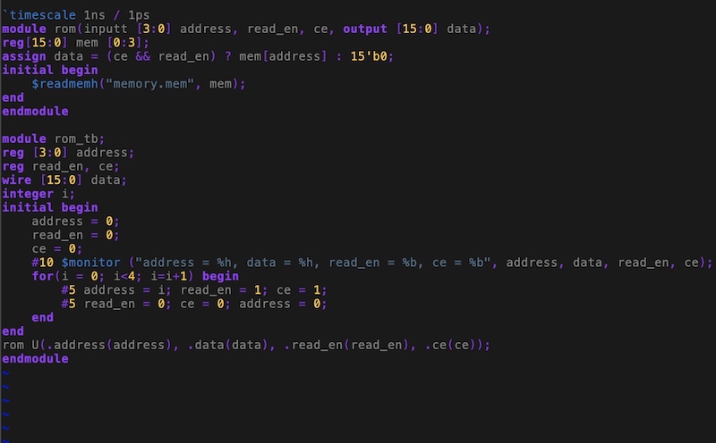
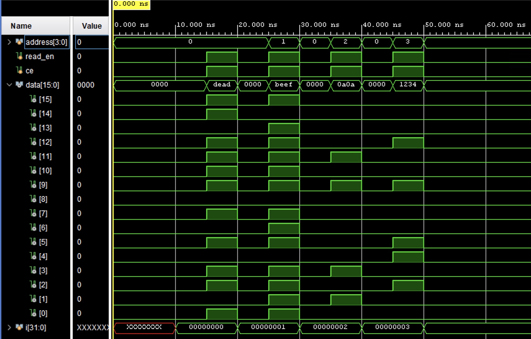
Figure 8. ROM memory using hex number code implementation with vivado simulation.

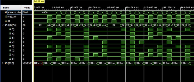
Figure 9. ROM memory using 8-bit binary code implementation with vivado simulation.
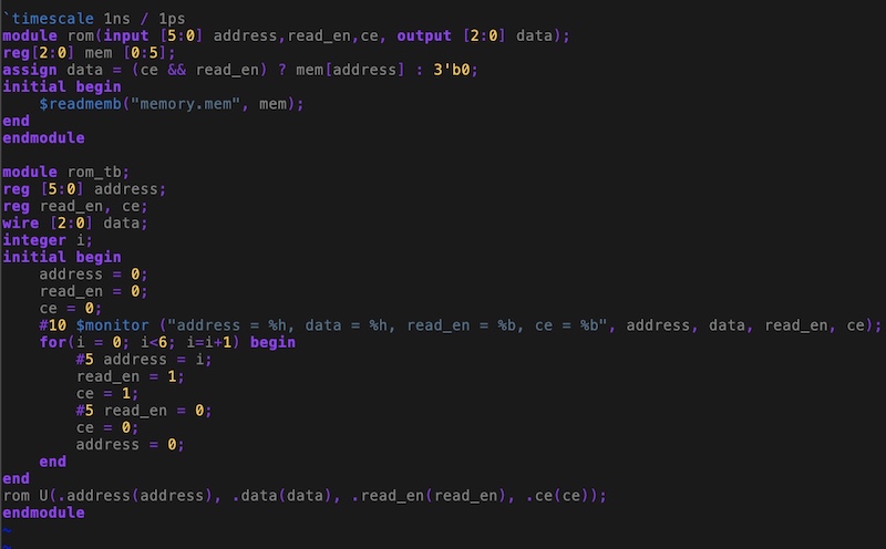
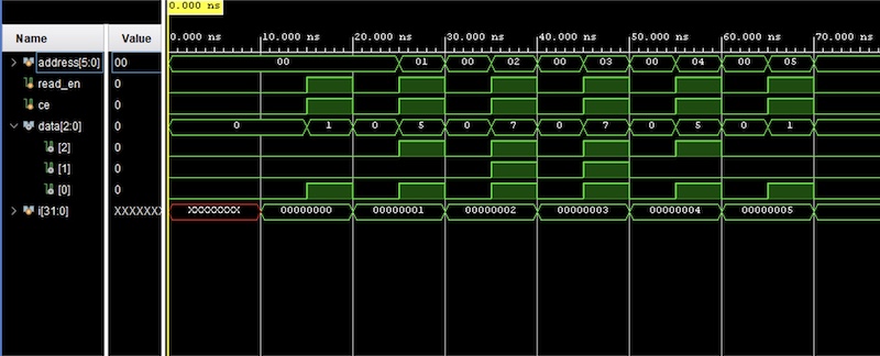
Figure 10. ROM memory using 3-bit binary code implementation with vivado simulation.
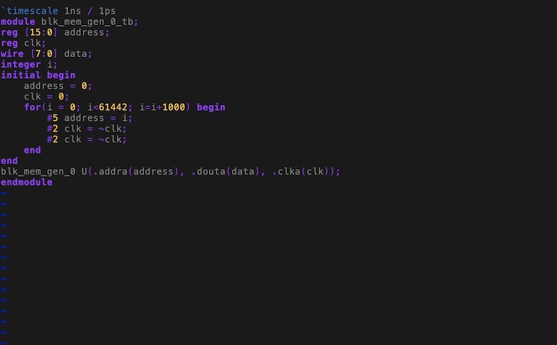
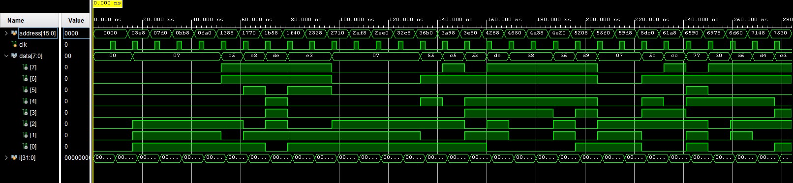
Figure 11. Extracting data from the ROM IP core code implementation with vivado simulation.
Discussion:
By completing this homwork, it allowed me to be more comfortable working with SR Latches, SR Flip Flops, D Latches, D Flip-Flops, JK Flip-Flops, T Flip-Flops, and Read Only Memory (ROM).
I liked this tutorial as it allowed us to see the different memory
capabilities available. Overall, I think this homework was a really fun
one and I look forward to the next!
............................................................