CE 433 Spring 2022 Combinational Blocks Tutorial Taylor Nakai tsnakai@fortlewis.edu
Introduction: In
this homework, we were given the tasks of implementing adders in
verilog
and simulating in vivado, implementing comparators and simulating in
vivado, using conditial statements and loops in verilog, implementing
decoders and simulating in vivado, implementing encoders and simulating
in vivado, implementing multiplexers and simulating in vivado,
implementing parity generators and checkers and simulating in vivado,
improving the home alarm system, improving the car parking system, and
implementing many of the modules on the Basys 3 board.
Task 1: In
task 1, we were giving the task of following the example to create both
a Half-Adder and Full-Adder. Once the code was implemented we were able
to run behavioral simulations to verify that the logic followed the
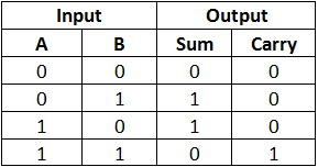
truth tables. The truth table for a half-adder is seen in Figure 1. The
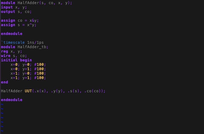
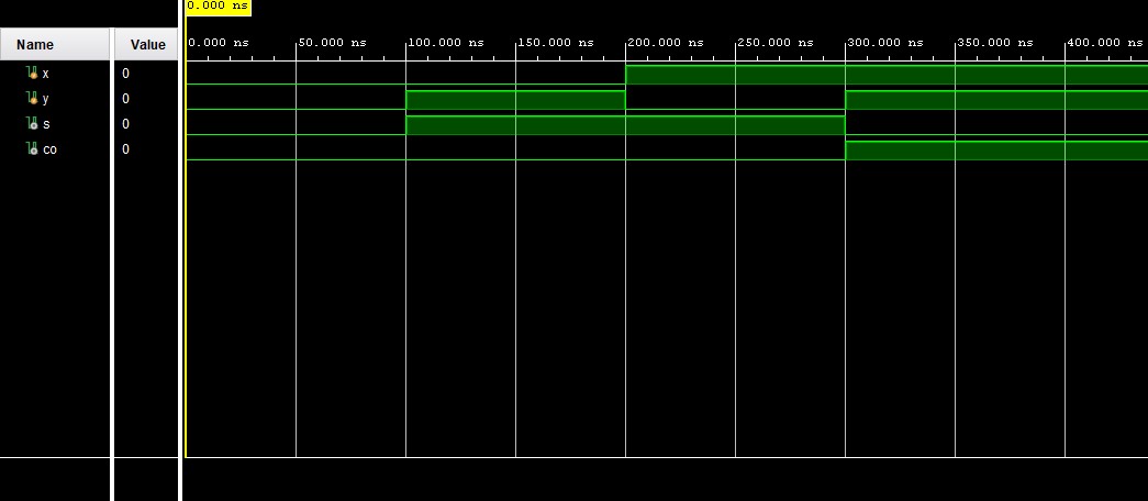
code and simulation results showing that the logic follows the truth
table is seen in Figure 2. The
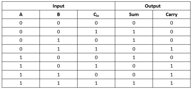
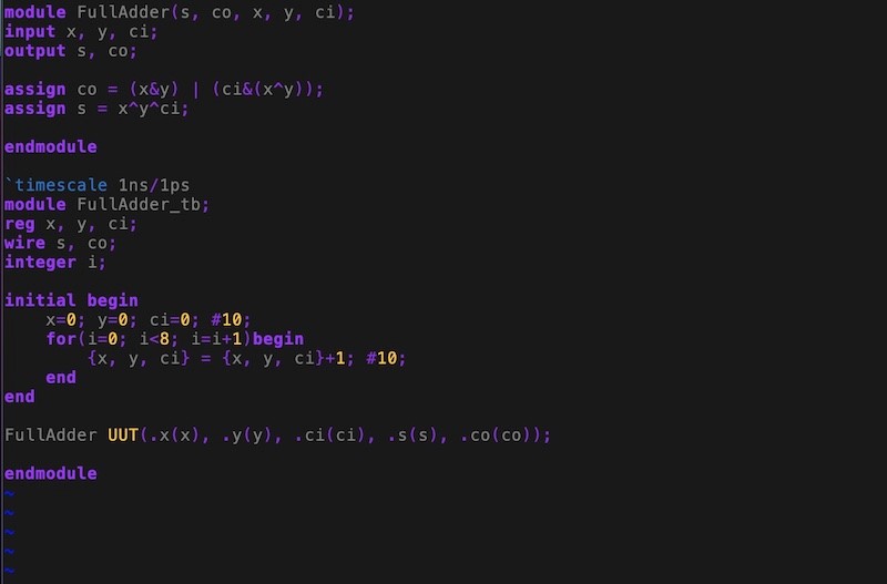
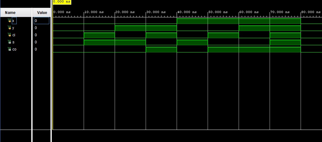
truth table for a full-adder is seen in Figure 3. The code and
simulation results showing that the logic follows the truth table is
seen in Figure 4.
Figure 1. Half-Adder truth table.
Figure 2. Half-Adder code example implemented with vivado simulation results.
Figure 3. Full-Adder truth table.
Figure 4. Full-Adder code example implemented with vivado simulation results. Task 2: In
task 2, we were given the task of implementing a testbench for the
one-bit comparator code given and simulate to ensure the logic follows
the truth table. Once the testbench was implemented we were able
to run a behavioral simulation to verify that the logic followed the
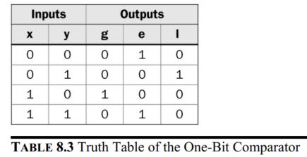
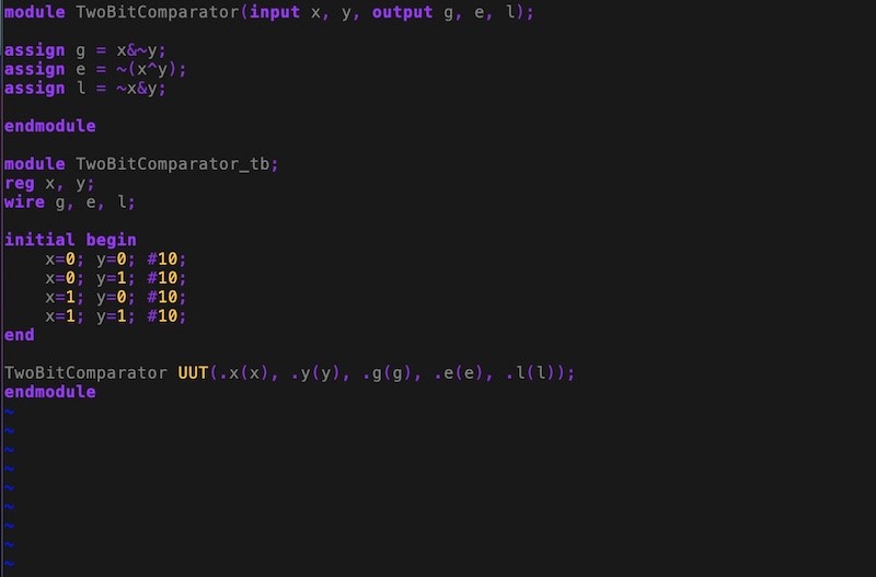
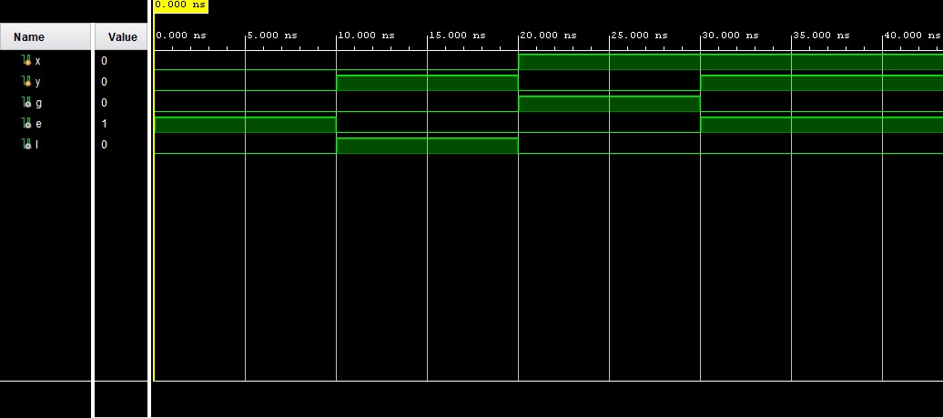
truth table. The truth table for a one-bit comparator is seen in Figure 5. The
code and simulation results showing that the logic follows the truth
table is seen in Figure 6.
Figure 5. One-bit comparator truth table.
Figure 6. One-bit comparator code example implemented with vivado simulation results.
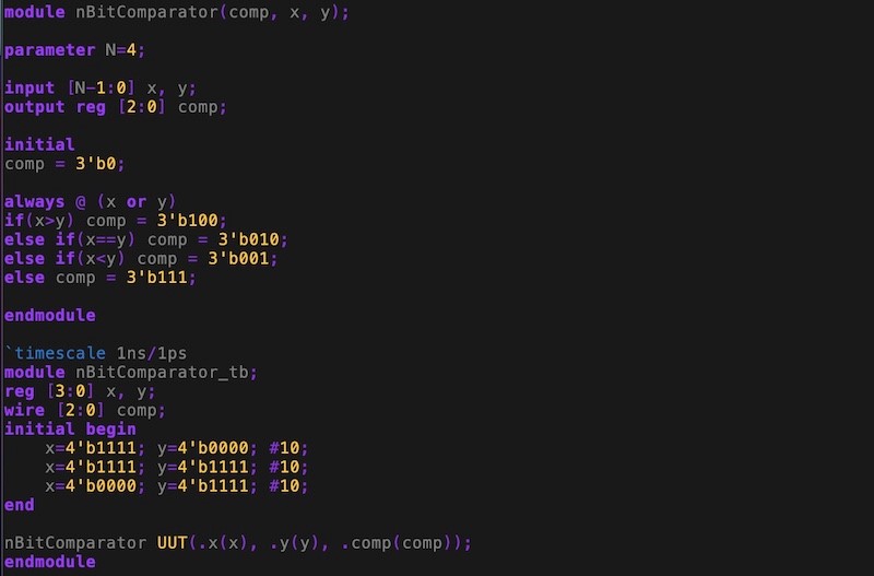
Task 3: In task 3,
we were given the task of implementing a testbench for the four-bit
comparator code given and simulate to ensure the logic follows
the truth table. Once
the testbench was implemented we were able
to run a behavioral simulation to verify that the logic was correct using three test cases that showed the different output. The
code and simulation results showing that the logic follows the truth
table, showing 3 test cases where the output is supposed to be
different, is seen in Figure 7. The rest of the cases would follow the
truth table if test, but only 3 were chosen to clearly show the
different outputs.
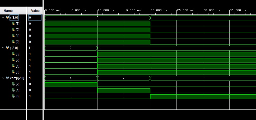
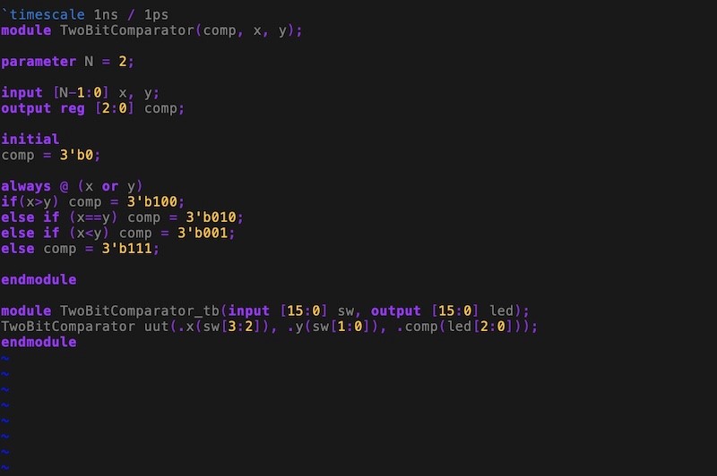
Figure 7.Four-bit comparator code example implemented with vivado simulation results.
Task 4: In
task 4, we were given the task of implementing a 2-bit comparator on
the Basys 3 board that uses the switches as inputs and the leds as
outputs. The code used to perform the on-board verification is shown in
Figure 8. Figure 9 shows the demonstration of the 2-bit comparator
being
implemented on the Basys 3 board.
Figure 8. Two-bit comparator code that is used to program the Basys 3 board.
Figure 9. Demonstration of the two-bit comparator on the Basys 3 board.
Task 5: In
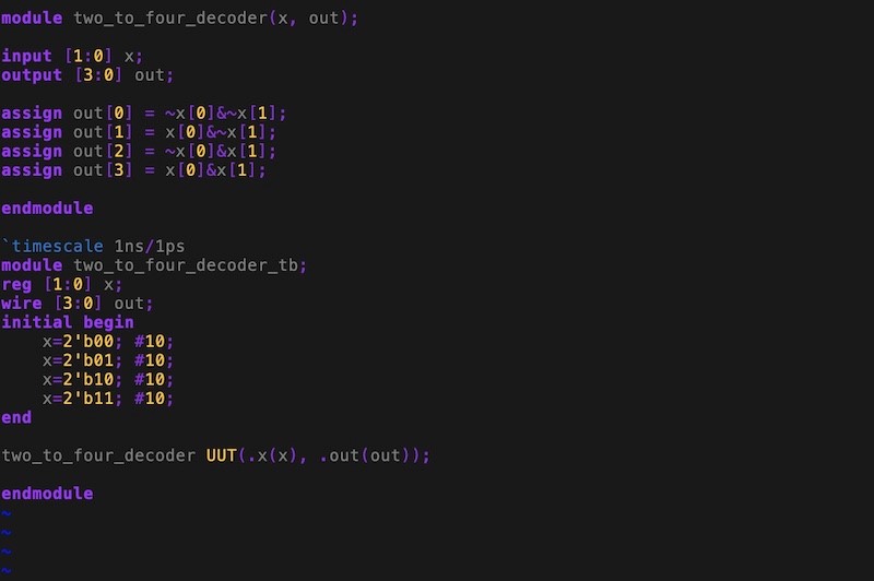
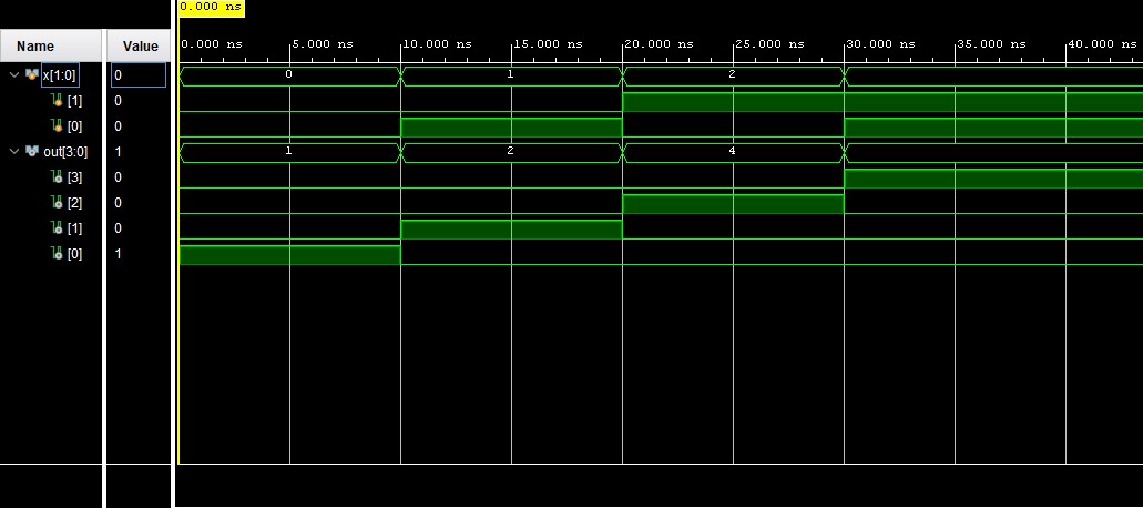
task 5, we were given the task design a 2-4 decoder and verify the
logic. We were able to build the module and run a simulation to verify
the logic as shown in Figure 10.
Figure 10. 2-4 Decoder code example implemented with vivado simulation results.
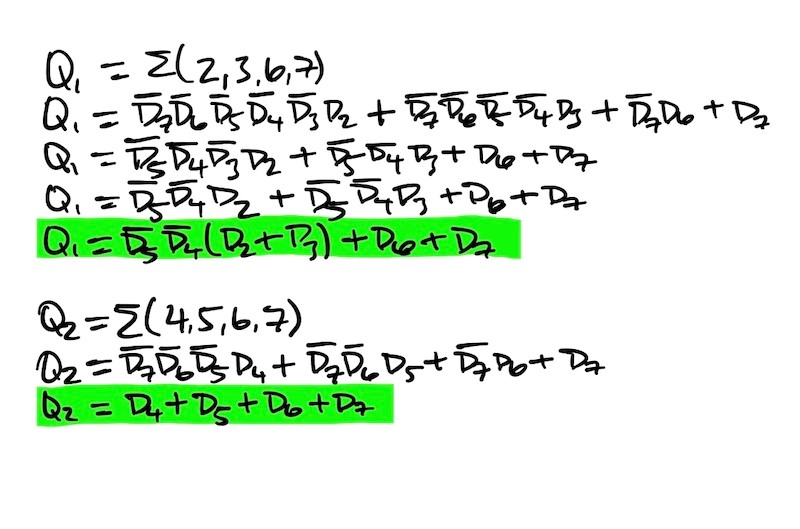
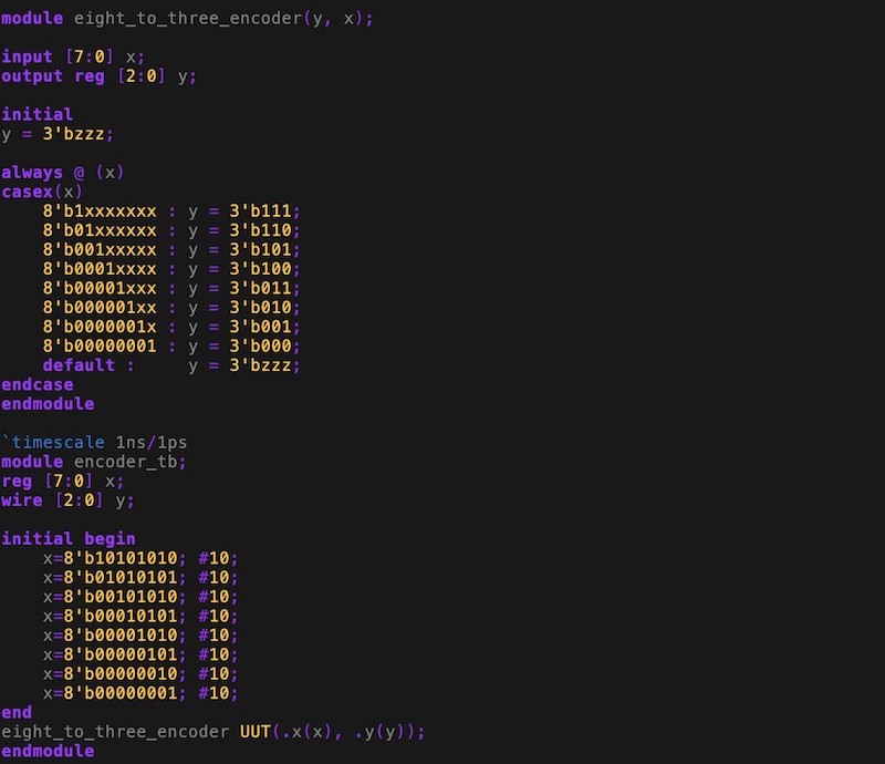
Task 6: In
task 6, for the 8x3 priority encoder we needed to derive Q1 and Q2,
build the module, and verify the logic through simulations. Q1 and Q2
were derived by hand shown in Figure 11. Once Q0, Q1, and Q2 were
derived we were able to build the module and perform a simulation to
verify the logic shown in Figure 12.
Figure 11. Hand derivation to determine the logic of Q1 and Q2.
Figure 12. 8x3 priority encodercode implemented with vivado simulation results.
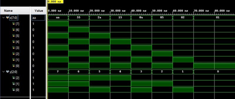
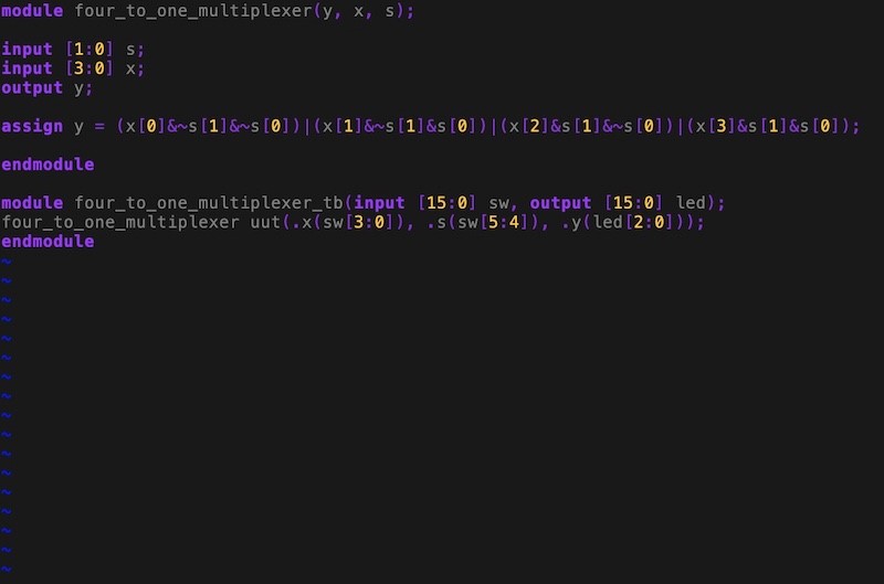
Task 7: In
task 7, we were given the task of implementing a 4-1 multiplexer on the
Basys 3 board. The code used to implement the 4-1 multiplexer is shown
in Figure 13. The programmed Basys 3 board showing the 4-1 multiplexer
logic is shown in Figure 14.
Figure 13. 4-1 Multiplexer code that is used to program the Basys 3 board.
Figure 14. Demonstration of the 4-1 Multiplexer on the Basys 3 board.
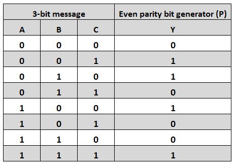
Task 8: In
task 8, we were given the task of design/verify an even parity
generator and checker in simulation and implement an even parity
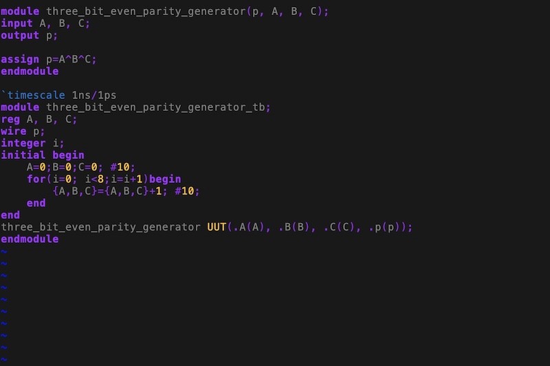
checker on the Basys 3 board. To begin, we needed to use the example of
the parity generator code shown in Figure 16. Once the testbench was
created, we were able to run a simulation shown in Figure 16. The
simulation results follow the truth table of a parity generator shown
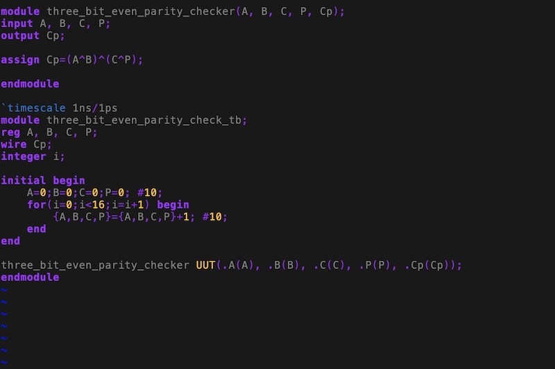
in Figure 15. Next, we need to design the parity checker and run a
simulation shown in Figure 18. The simulation results also followed the
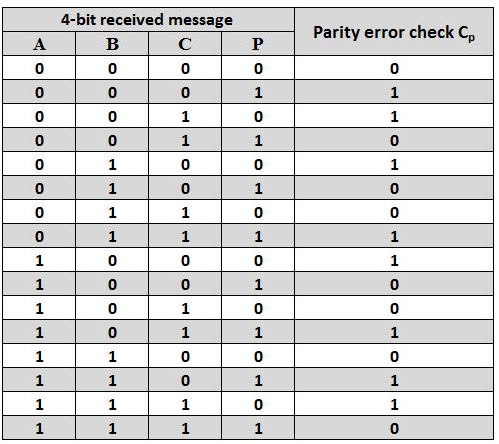
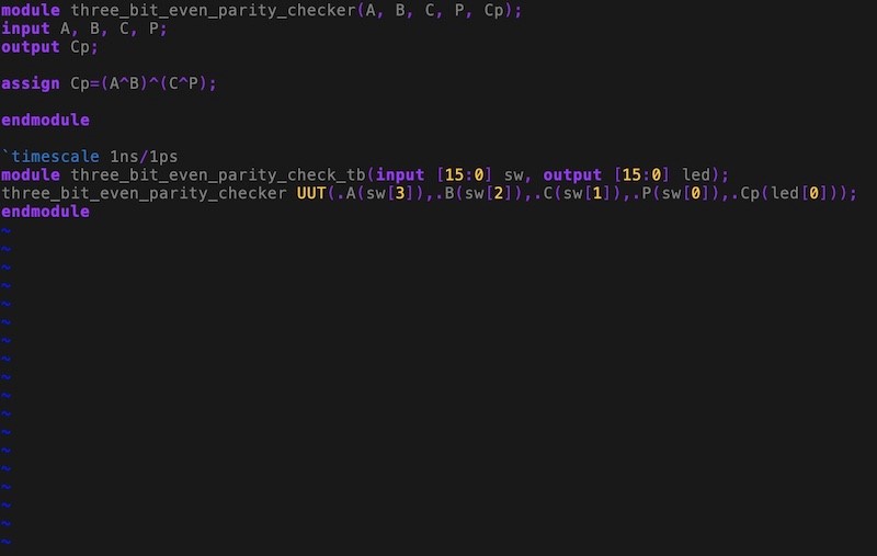
truth table of a parity checker shown in Figure 17. Finally, knowing
that the logic was correct we were able to implement the even parity
checker on the Basys 3 shown in Figures 19 and 20.
Figure 15. Truth table of 3-bit even parity generator.
Figure 16. 3-bit even parity generatorcode implemented with vivado simulation results.
Figure 17. Truth table of even parity checker.
Figure 18. Even parity checker code implemented with vivado simulation results.
Figure 19. Even parity checker code that is used to program the Basys 3 board.
Figure 20. Demonstration of the even parity checker on the Basys 3 board.
Task 9: In
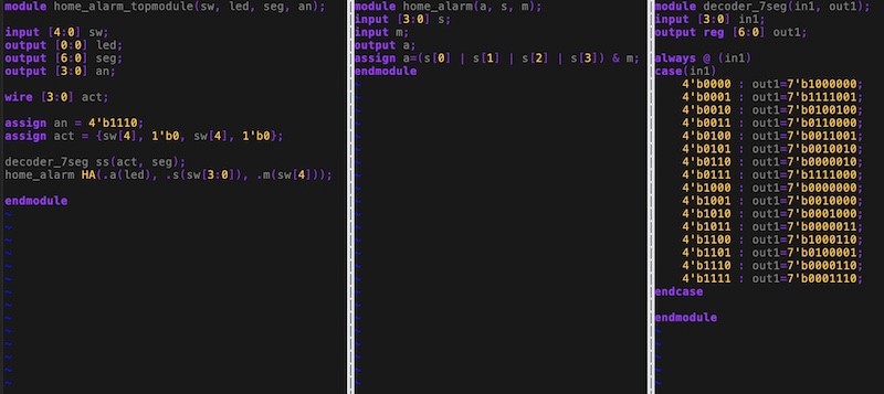
task 9, we were given the task of implementing the improved home alarm
system and car parking spot counting system on the Basys 3 board. The
improved home alarm system integrated the seven-segment display so that
when the system is armed it will display a 'A' and when the system is
not armed it will display an 'O'. In order to implement this we needed
to use the code from the previous homework and add the seven-segment
display decoder module to the system. The module converts the provided
hexadecimal number to the corresponding seven-segment display pattern.
The code used for the improved home alarm system is shown in Figure 21.
In Figure 22, it shows a demonstration of the system implemented on the
board where if the switch to activate the system is on then an 'A' will
be displayed and when any of the 4 sensors are triggered then the alarm
will turn on. When the switch to activate the system is off then an 'O'
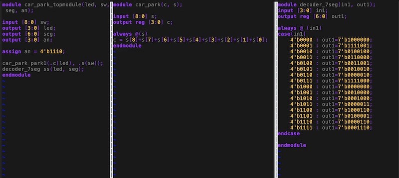
will be displayed. The improved car parking spot counting system integrated the seven-segment display so it will display the number of occupied slots up to 9 cars. In
order to implement this we needed to use the code from the previous
homework and add the seven-segment display decoder module to the system.The code used for the improved car parking spot counting system is shown in Figure 23.In
Figure 24, it shows a demonstration of the system implemented on the
board where if any of the switch are turned on, then it will count that
as a spot occupied and display the number on the seven-segment display.
Figure 21. Improved Home Alarm Sytem code that is used to program the Basys 3 board.
Figure 22. Demonstration of the Improved Home Alarm System on the Basys 3 board.
Figure 23. Car Park Sytem code that is used to program the Basys 3 board.
Figure 24. Demonstration of the Improved Car Parking Spot Counting System on the Basys 3 board.
Discussion:
By completing this homwork, it allowed me to be more comfortable
working with adders, comparators, decoders, encoders, multiplexers, and
parity generators and checkers. It was good to have a refresher on
these important components. I really enjoyed performing the on-board
verification. I think that this homework has really helped me to be
more comfortable using vivado and implement the on-board verification.
Overall, I think this homework was a really fun one and I look forward
to the next! ............................................................