CE 433 Spring 2022 Data Types Tutorial Taylor Nakai tsnakai@fortlewis.edu
Introduction: In
this homework, we looked at data types, operators, and combinational
logic. We reviewed number systems, worked with fixed-point
representation and floating-point representation, worked
with fixed-point and floating-point arithmetic, learned more about
net/data types in verilog, and working more on building combinational
logic designs. We were tasked with representing decimal numbers in
fixed point representation, representing decimal numbers in floating
point representation, performing floating point addition/subtraction,
and creating combinational logic designs.
Task 1: In
task 1, we were tasked with converting decimal numbers to their fixed
point representations or their floating point respresentation, as shown
in Figure 1 and 2.
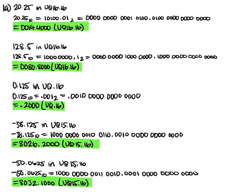
Figure 1. Representing decimal number in fixed point representation.
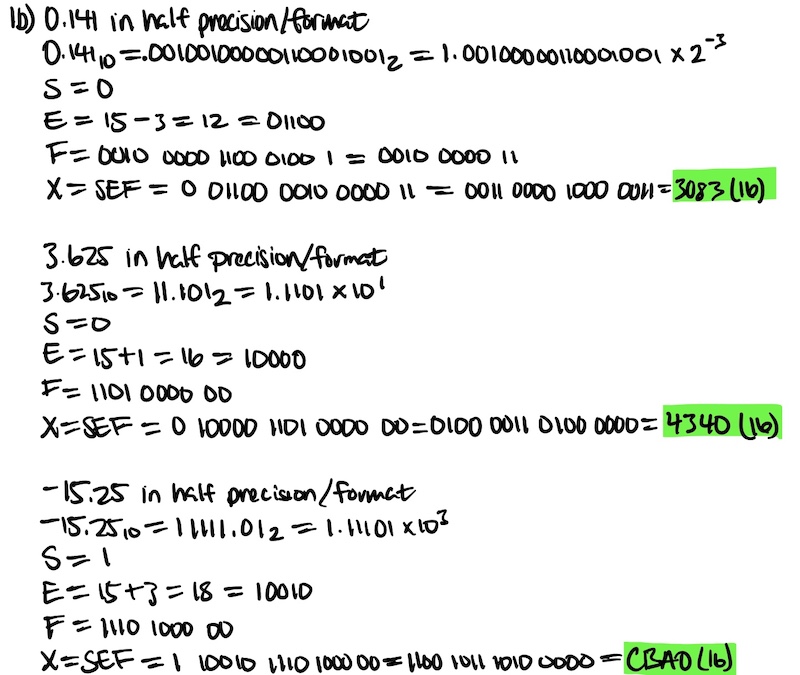
Figure 2. Representing decimal numbers in floating point representation.
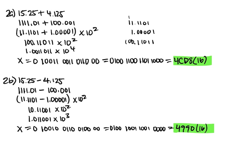
Task 2: In task 2, we were tasked to show the process of floating point addition/subtraction as shown in Figure 3.
Figure 3. Showing the process of floating point addition and subtraction.
Task 3: In
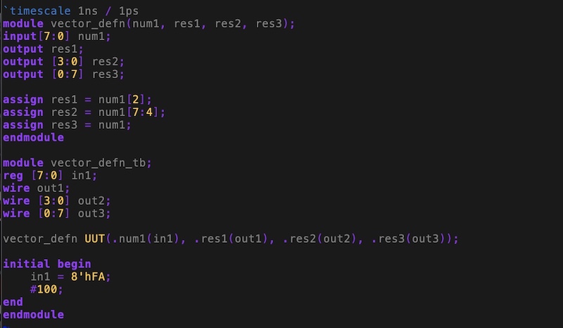
task 3, we were given an example that deals with vectors. The example
shows how to work with vectors by declaring them, determining MSB and
LSB, and assigning values to specific bits. The code used is shown in
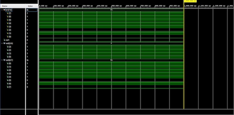
Figure 4 with the resulting simulation being displayed in Figure 5. We
can see that the results are as we expect as in the 'in' vector is
assigned an 8 bit value of '11111010', 'out1' is being assigned '0'
since it was assigned the value of in[2] which is '0', 'out2' is being
assigned the 4 MSB of 'in' which is '1111', and 'out3' is being
assigned the same 8 bit value as 'in' but with out3[0] being the MSB
and out3[7] being the LSB.
Figure 4. Code for example showing the use of vectors.
Figure 5. Showing the simulation results using vectors.
Task 4: In
this task, we were to build three different combinational logic designs
and verify them on our FPGA. The first combinational logic design was a
home alarm system with the code being shown in Figure 6 and the
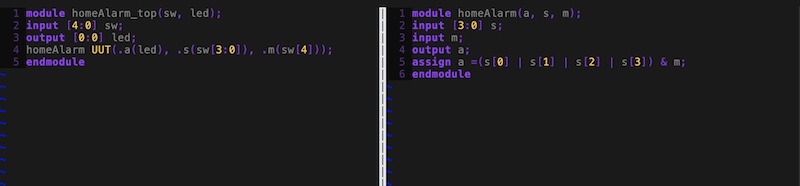
verification being shown in Figure 7. The logic basically shows that if
the switch to activate the system is on and any of the 4 sensors are
triggered then the alarm will turn on, which is shown in the
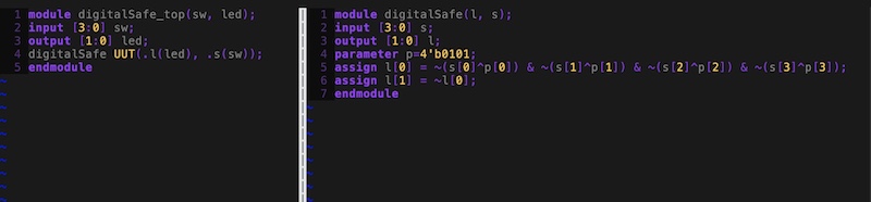
verification. The second combinational logic design was a digital safe
system with the code being shown in Figure 8 and the verification being
shown in Figure 9. The logic shows that the safe will only open when
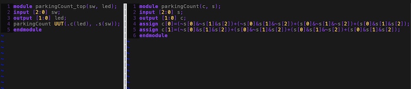
the correct password of '0101' is inputted. The third combinational
logic design was a 3 car parking occupied spots counting system with
the code bing shown in Figure 10 and the verification being done in
Figure 11. The logic basically follows the truth table that was given.
Figure 6. Code used for builing the home alarm system.
Figure 7. Verifying the home alarm system on the FPGA.
Figure 8. Code used for builing the digital safe system.
Figure 9. Verifying the digital safe system on the FPGA.
Figure 10. Code used for builing the 3 car parking occumpied spots counting system.
Figure 11. Verifying the 3 car parking occupied spots counting system.
Discussion: By
completing this homwork, it allowed me to be more comfortable with
representing numbers in their fixed point representation, their
floating point representation, addition/subtration of floating point,
vectors, and combinational logic design. This was a very good homework
to work on these aspects. I really enjoyed performing the on-board
verification. I think that these skills will be useful for the future.
Overall, I think this homework helped clear up some things and
reinforce the important topics and I look forward to the next.
............................................................