ENGR338 Lab 2021
Spring
Lab 1 Review Superposition, Thevenin's Equivalent Circuit, and LTSpice
Name: Sean
Eaton
Email:
smeaton@fortlewis.edu
Reviewing Superposition, Thevenin's Equivalent Circuit, and LTSpice
Introduction
In
this lab we were tasked with reviewing various circuit analysis
techniques. Superposition theory was used to analyze the circuit in
Task 1 while Task 2 required us to find the Thevenin's Equivalent
circuit. In addition to this, we had to verify our calculations with an
LTSpice simulation. It was also required of us to implement the LTSpice
simulation using only spice code.
Tasks
Task 1: Review Superposition and Spice
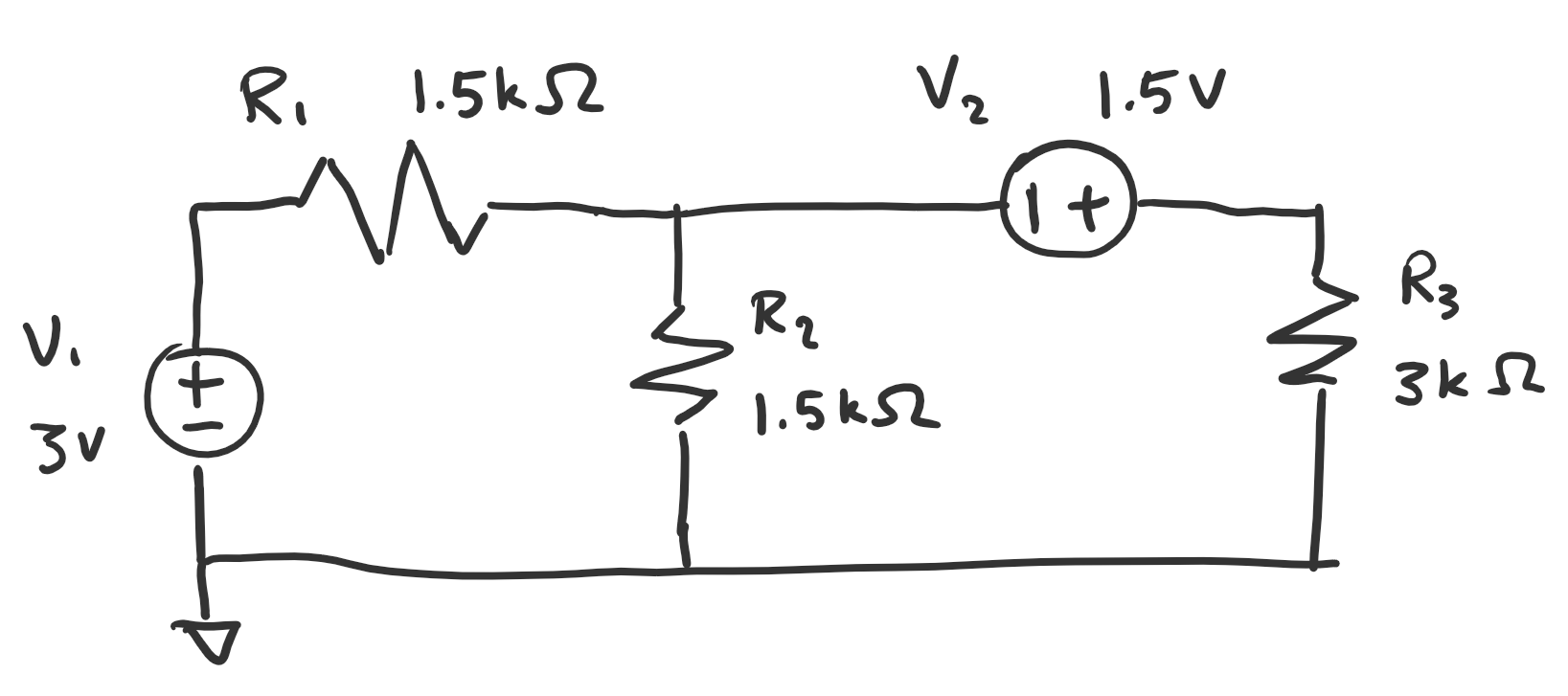
For
the following circuit use superposition theory to calculate all of the
voltages and currents. Verify calculations using LTSpice and Spice code
only.
Figure 1: Task 1 Schematic.
Task 2: Review Thevenin's Equivalent Circuit and RC time delay
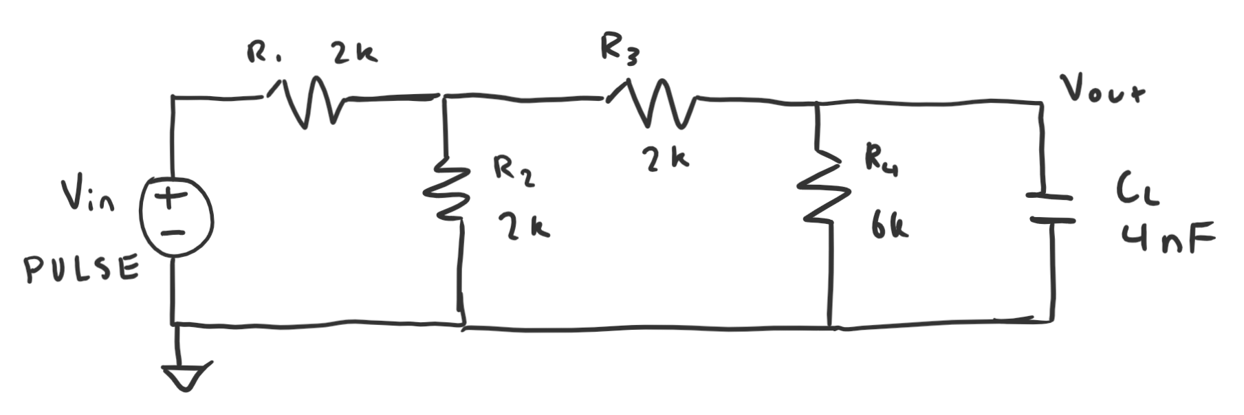
For
the following circuit, we treated CL as the load and converted
everything to the left side of it to its Thevenin's Equivalent circuit.
The PULSE function was left to us to define. The only requirement was
that it needed to show a nice time delay plot. We then had to calculate
the time delay and compare it to the measured time delay.
Figure 2: Task 2 Schematic.
Results
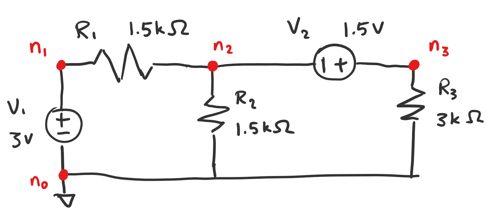
Task 1: Figure 3 shows the nodes I defined on the schematic.
Figure 3: Nodes labelled on the schematic.
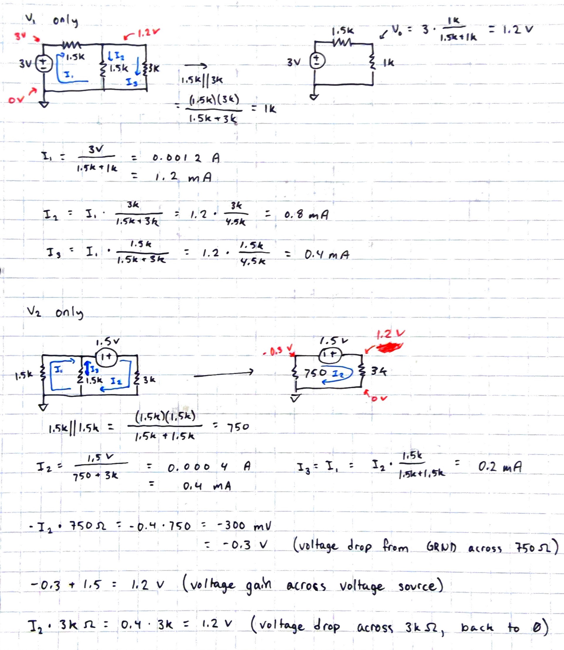
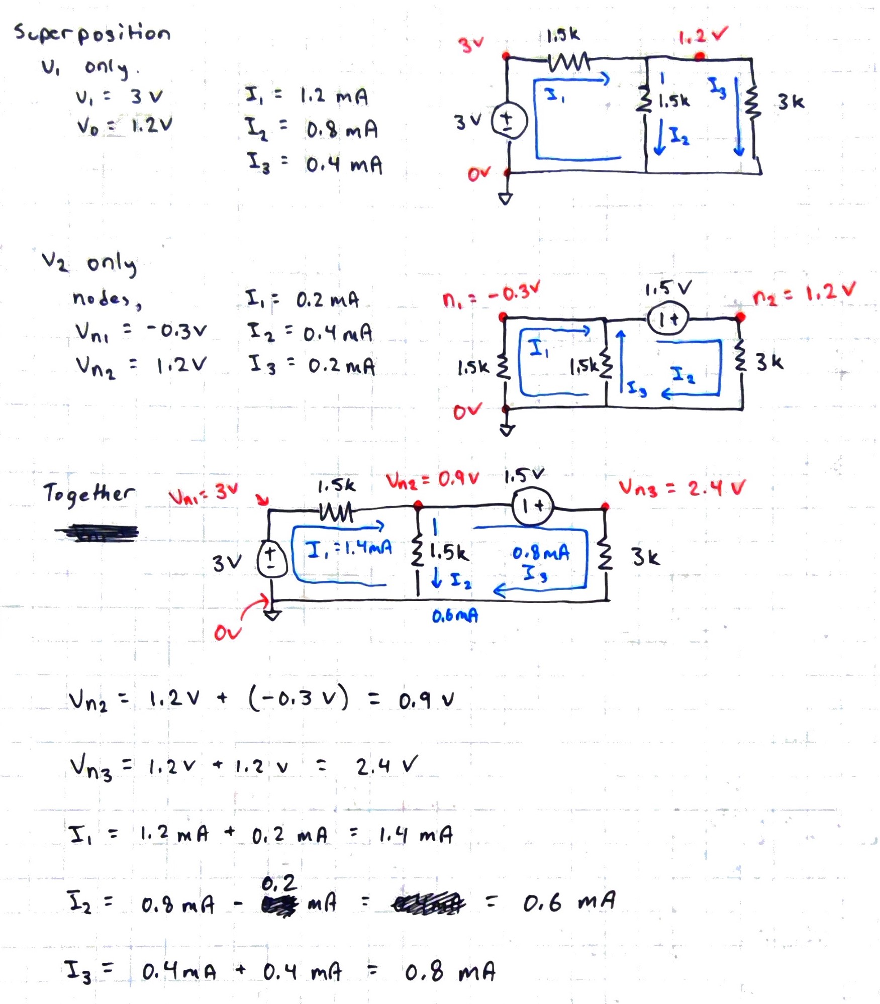
For
superposition we analyze the circuit using each voltage source on its
own. Figure 4 below shows the calculations for voltage source 1 and
voltage source 2 on their own. The voltages at each node was figured
out as well as the currents running through each branch.
Figure 4: Voltage and current calculations.
After
finding the node voltages and currents for the circuits, the results
are combined to get the node voltages and currents for the circuit
containing both voltage sources. Figure 5 shows the results being put
together to get the final results for the original circuit.
Figure 5: Final superposition calculations.
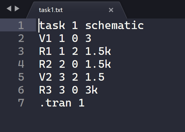
This circuit was then designed in LTSpice using the following Spice code.
Figure 6: Spice code for schematic 1.
In table 1, the calculated results and the simulated results for the node voltages will be compared.
| Nodes | Calculated | Simulated |
| n0 | 0V | 0V |
| n1 | 3V | 3V |
| n2 | 0.9V | 0.9V |
| n3 | 2.4V | 2.4V |
Table 1: Calculated node voltages compared to simulated node voltages.
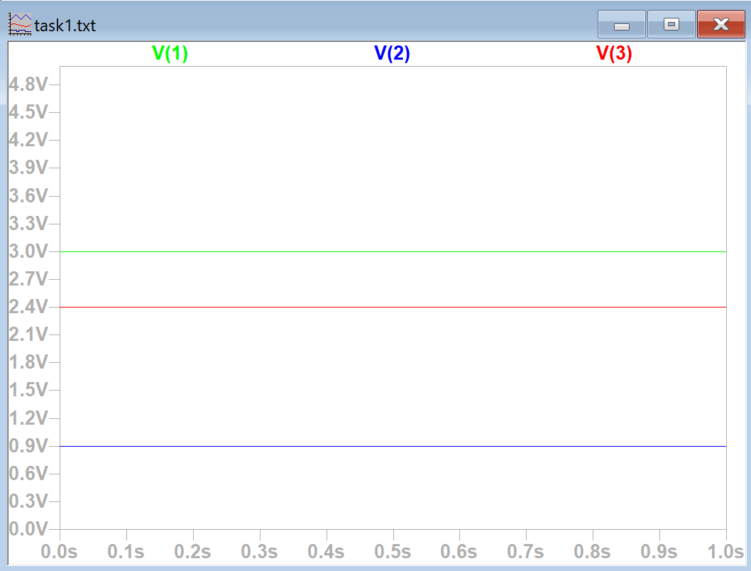
The figure below shows the plotted simulated results for the node voltages.
Figure 7: Plotted node voltages for nodes 1, 2, and 3.
In
table 2, the calculated results and the simulated results for the
current branches are compared. They correspond to the resistor numbers.
| Currents | Calculated | Simulated |
| I1 | 1.4 mA | 1.4 mA |
| I2 | 0.6 mA | 0.6 mA |
| I3 | 0.8 mA | 0.8 mA |
Table 2: Calculated currents compared to simulated currents.
In Figure 8 the simulated results were plotted in LTSpice.
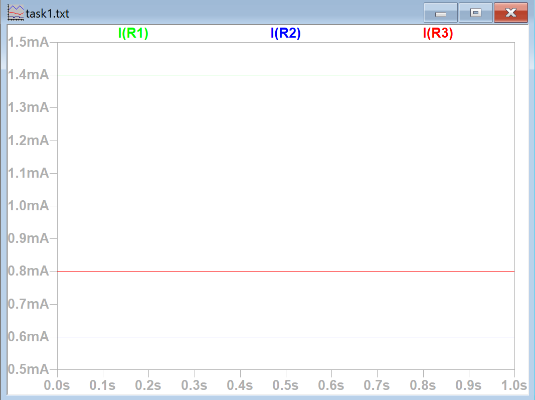 Figure 8: Plotted currents for resistors 1, 2, and 3.
Task 2:
For
task 2 the Thevenin's equivalent circuit and time delay was worked out
before defining the PULSE function. Figures 9 and 10 show the
calculations for the Thevenin's equivalent circuit and the time delay.
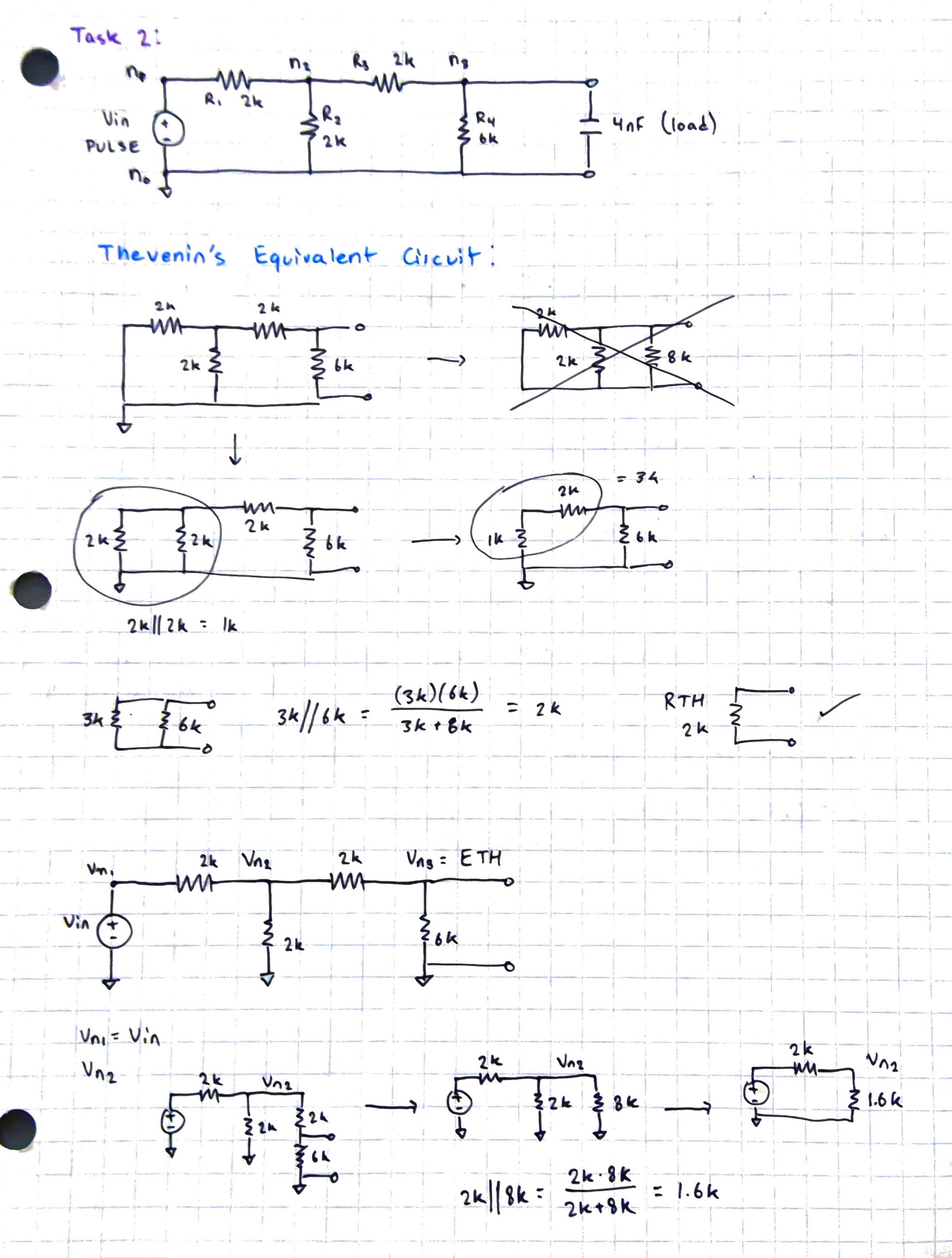 Figure 9: Calculations for finding the Thevenin's equivalent resistance.
The
crossed out circuit above in figure 9 had a mistake with the 2k ohm and
6k ohm resistors and was crossed out. In the end RTH was found to be 2k
ohms. Some beginning work to find the equivalent voltage is shown on
the bottom as well.
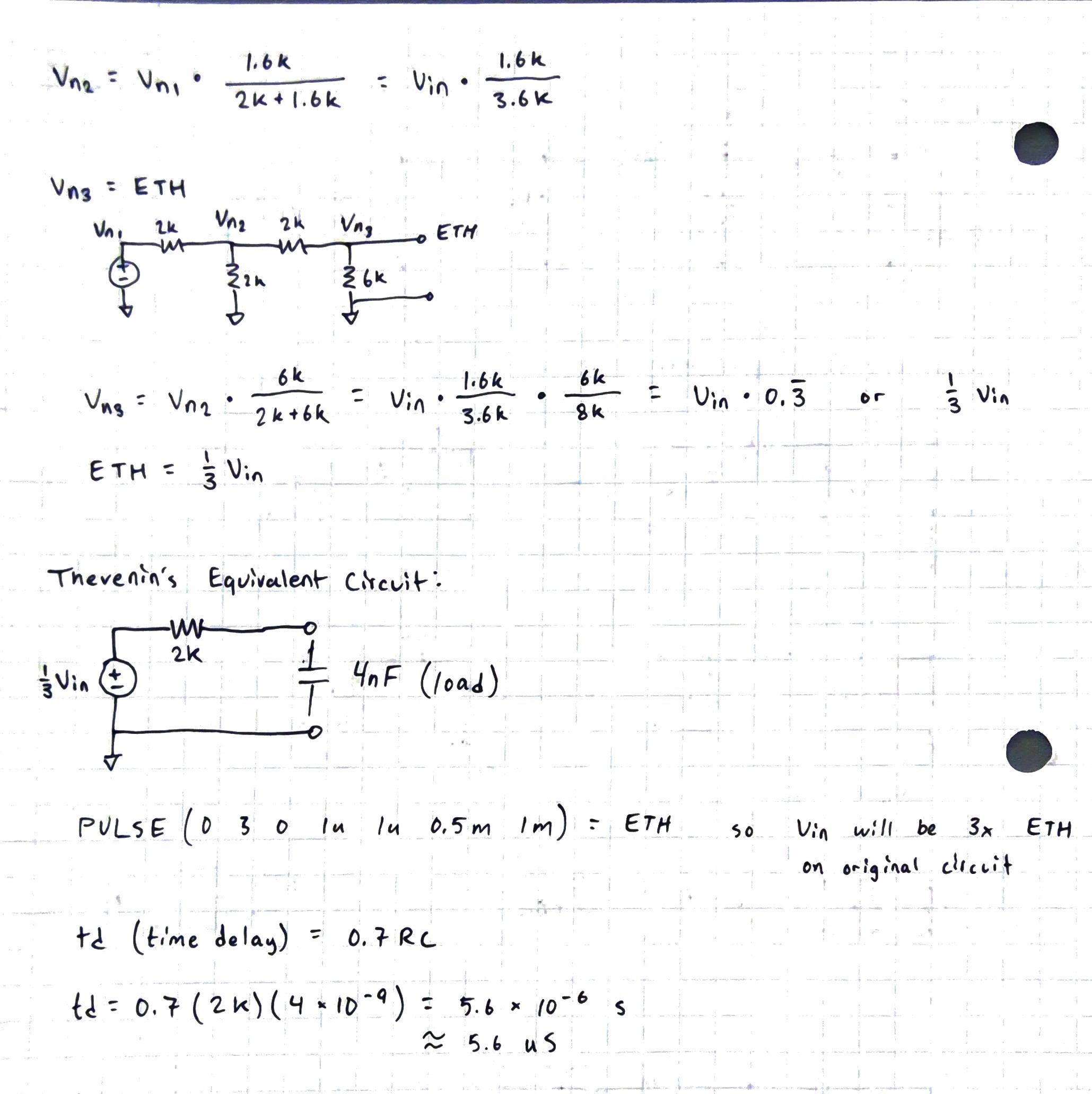 Figure 10: Calculations for finding Thevenin's equivalent voltage and the time delay of the circuit.
The
Thevenin's equivalent voltage was found to be one third of the input
voltage of the original circuit. For the simulation I decided to
implement the Thevenin's equivalent circuit instead of the original
circuit. The calculated time delay was found to be 5.6 microseconds.
The simulated time delay was measured to be 5.8 microseconds as shown
below in Figure 11.
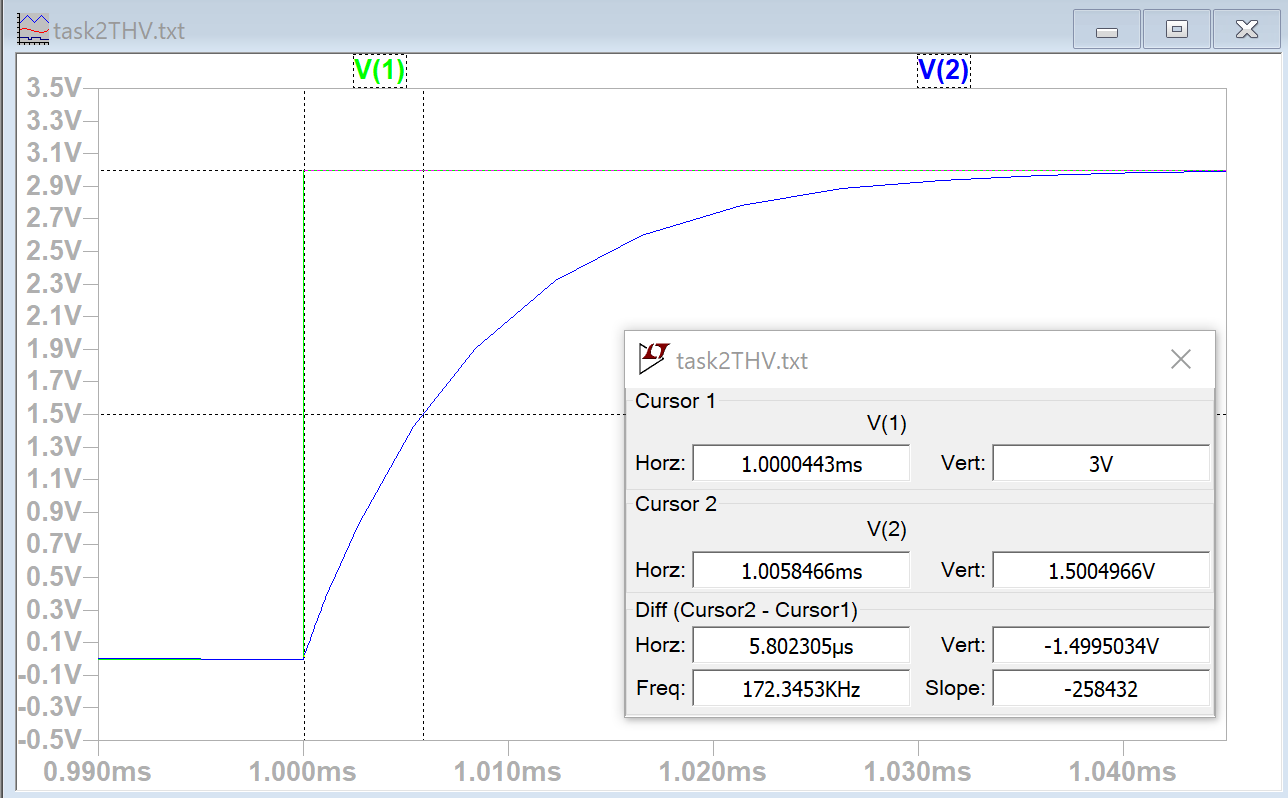 Figure 11: Measuring time delay between ETH and Vout in the Thevenin's equivalent circuit.
The spice code for task 2's Thevenin's equivalent circuit is shown below in Figure 12.
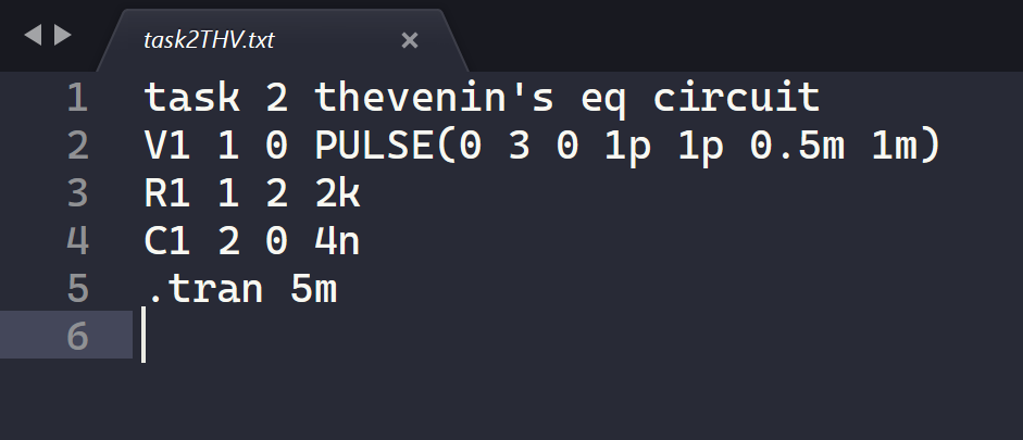 Figure 12: Schematic 2's Thevenin's equivalent circuit spice code.
Discussion
This
lab was a good refresher on superposition and finding the Thevenin's
equivalent circuit as well as using spice code in LTSpice which I
hadn't used very often.
In task 1 the simulation results were not
initially correct because my spice code defined the nodes connecting
the second voltage source in the wrong order. It was helpful to learn
more about spice code and how the nodes should be listed in the
direction of the voltage drop and not how I would normally think about
the direction of the nodes.
In task 2 I decided to simulate the
Thevenin's equivalent circuit because it was simpler than the original
schematic although I did simulate the original circuit. Since ETH
equals one third of the original circuit's voltage input the plotting
between Vin and Vout also looked better on the Thevenin's equivalent
voltage compared to the original circuit. The difference between the
calculated and simulated time delay is most likely due to how it was
measured in LTSpice. If the cursor could be set to exactly 1.5V the
measured value should match the calculated value.