CE 432 2021 Fall Joystick and Stepper Motor Tutorial
Sophie Turner
sjturner@fortlewis.edu
Joystick and Stepper Motor Tutorial
1. Introduction This tutorial introduced using a joystick. The
first task is to use the joystick and serial monitor to see the y-axis, x-axis,
and switch readings. Task 2 uses Open-Smart 2.4 GHz transceivers to transmit
data from the joystick and the other wireless modules receives data. The third
task uses the joystick to control a NEMA17 stepper motor.
2. Methods Two Arduino UNO boards, a joystick, two
Open-Smart 2.4 GHz transceivers, a NEMA17 stepper motor, DC power supply, and
47uF capacitor were used for this lab. For a more detailed methods section go
to Joystick/Stepper Motor Tutorial.
3. Results
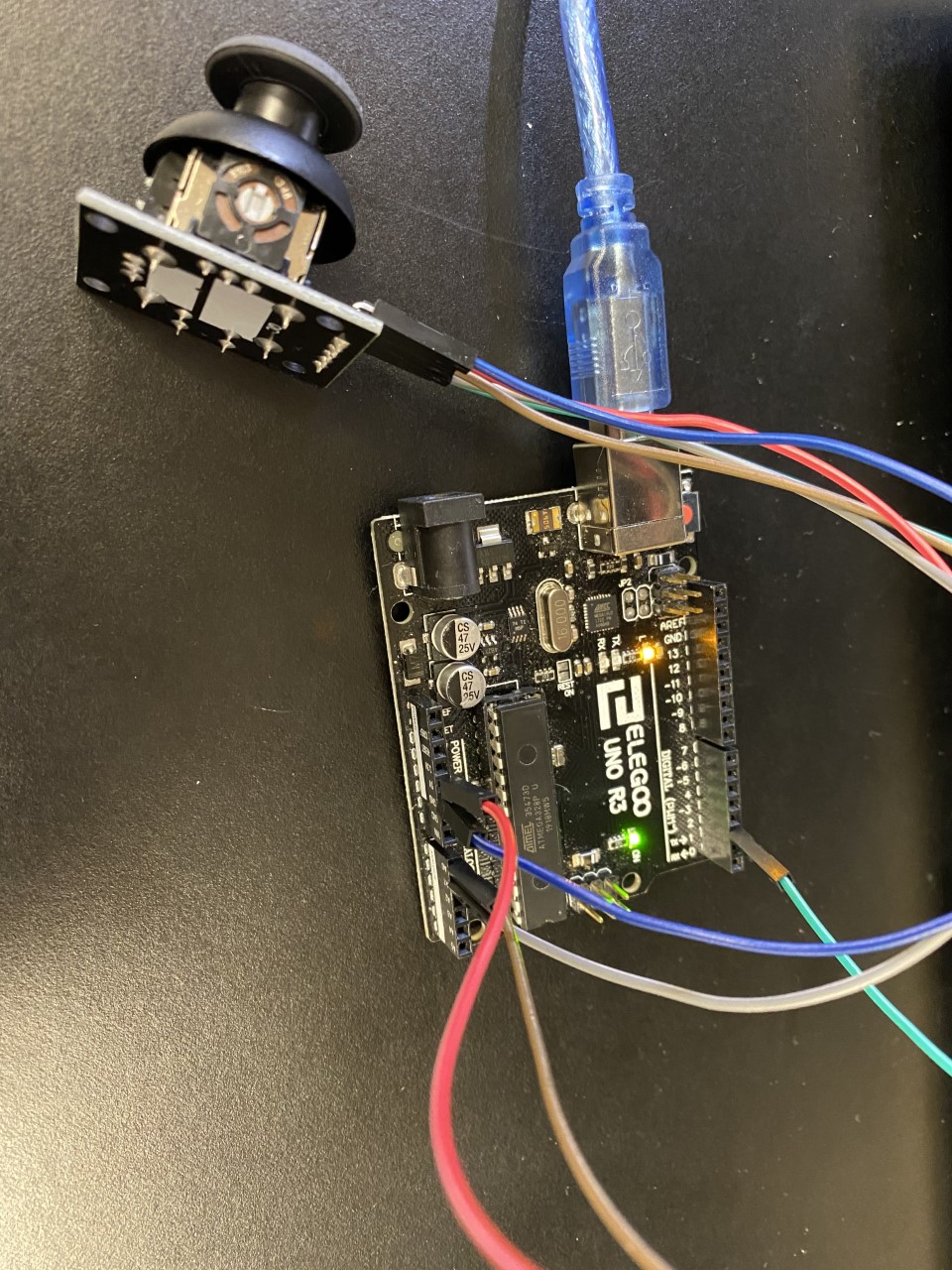
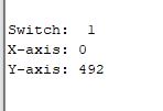
Task 1. Task 1 was to connect the thumb joystick to an
Arduino UNO. The joystick was tested using the serial monitor. When the
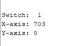
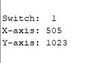
joystick was pushed to the far-left y-axis was 0. If pushed to the far right
the y-axis was 1023 because that is the maximum digital output for the Arduino.
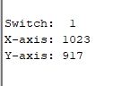
Similarly, if the joystick was pushed up then the x-axis read 1023 and down was
0. Figure 1. Hardware connections for the joystick to the Arduino UNO.
Figure 2. Result when the joystick was pushed to the far left.
Figure 3. Result when the joystick was pushed to the far right.
Figure 4. Result when the joystick was pushed up.
Figure 5. Result when the joystick was pushed down.
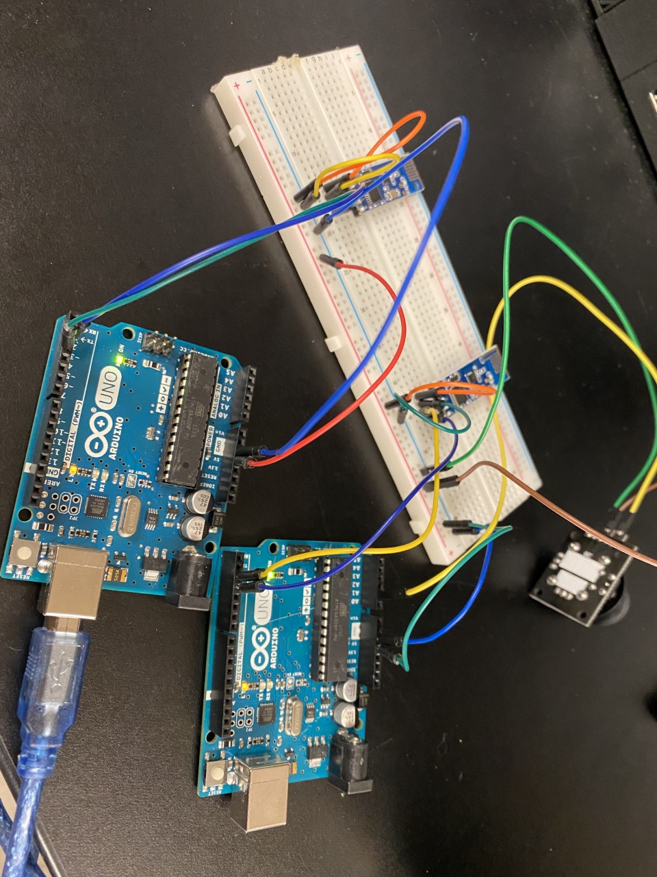
Task 2. For Task 2 two wireless modules were connected,
one as a reviver and one as a transmitter. Two Arduino UNOs were used to
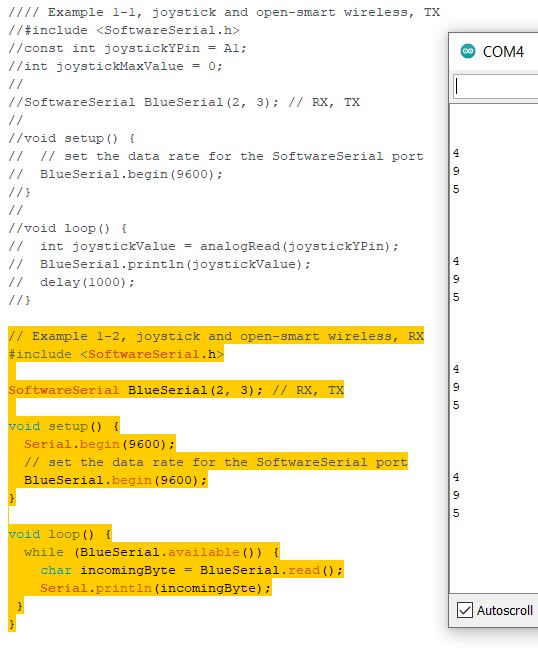
connect the wireless modules and separate code was loaded on each of them. 495
is about the mid-point for the joystick which shows up in the serial monitor
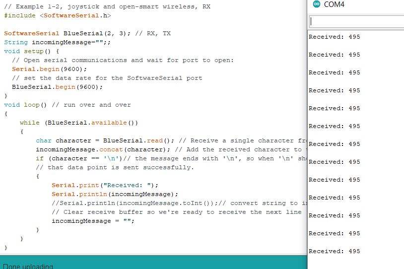
in Figure 6 when it is at rest. A new line is created after each number since each digit is a
character. In Figure 8 code is concatenated into a string making the output
easier to read.
Figure 6. Reciver and transmitter wiring and setup. Figure 7. The receiver output
as characters.
Figure 8. The receiver output concatenated
into a string.
Task 3. The wireless modules and joystick are used to control a NEMA17 stepper motor. A
A4988 driver is added to the ciricut as well. A 12V DC power supply and
47uF capacitor was connected to the driver in order for the motor to
spin. The y-axis on the joystick controls the direction of which the
motor spins.
Figure 9. Demonstrating the motor driver spinning with the y-axis movement of the joystick.
2. Discussion The homework was successfully completed. There
is a delay between the joystick and the motor driver which can be fixed within
the code. I was able to understand and gain experience using the joystick as
well as working with transmitting and receiving wireless modules. I was also
able to gain experience and understanding the basics of the driver and stepper motor.